Altera Video and Image Processing Suite User Manual
Page 242

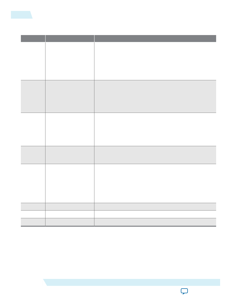
Table 18-6: Switch II Control Register Map
The table below describes the control register map for Switch II IP core.
Address
Register
Description
0
Control
Bit 0 of this register is the
Go
bit.
• Writing a 1 to bit 0 starts the IP core.
• Writing a 0 to bit 0 stops the IP core.
Bit 1 of this register is the interrupt enable bit.
• Setting this bit to 1 enables the switching complete interrupt.
1
Status
Bit 0 of this register is the
Status
bit, all other bits are unused.
• Reading a 1 from bit 0 indicates the IP core is running—video
is flowing through it.
• Reading a 0 from bit 0 indicates that the IP has stopped
running.
2
Interrupt
Bit 0 is the interrupt status bit. When bit 0 is asserted, the
switching complete interrupt has triggered.
Because the Switch II IP core can only change routing configura‐
tion at the end of a video frame, this interrupt triggers to indicate
that the requested reconfiguration has completed.
3
Output Switch
Writing a 1 to bit 0 indicates that the video output streams must
be synchronized; and the new values in the output control
registers must be loaded.
4
Dout0 Output Control
A one-hot value that selects which video input stream must
propagate to this output. For example, for a 3-input switch:
• 3'b000 = no output
• 3'b001 = din_0
• 3'b010 = din_1
• 3'b100 = din_2
5
Dout1 Output Control
As
Dout0 Output Control
but for output
dout1
.
...
...
...
15
Dout11 Output Control
As
Dout0 Output Control
but for output
dout11
.
18-6
Video Switching Control Registers
UG-VIPSUITE
2015.05.04
Altera Corporation
Video Switching IP Cores
