Altera Video and Image Processing Suite User Manual
Page 93
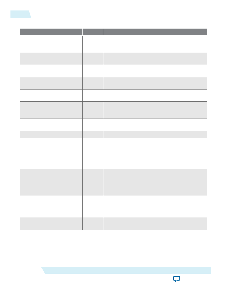
Table 4-19: Clocked Video Output II Signals
Signal
Direction
Description
main_reset_reset
Input
The IP core asynchronously resets when you assert this
signal. You must deassert this signal synchronously to the
rising edge of the clock signal.
main_clock_clk
Input
The main system clock. The IP core operates on the rising
edge of this signal.
din_data
Input
din
port Avalon-ST
data
bus. This bus enables the
transfer of pixel data into the IP core.
din_endofpacket
Input
dout
port Avalon-ST
endofpacket
signal. This signal is
asserted when the downstream device is ending a frame.
din_ready
Output
din
port Avalon-ST
ready
signal. This signal is asserted
when the IP core function is able to receive data.
din_startofpacket
Input
din
port Avalon-ST
startofpacket
signal. Assert this
signal when the downstream device is starting a new
frame.
din_valid
Input
din
port Avalon-ST
valid
signal. Assert this signal when
the downstream device produces data.
din_empty
Input
underflow
Output
Clocked video underflow signal. A signal corresponding to
the underflow sticky bit of the
Status
register synchron‐
ized to
vid_clk
. This signal is for information only and
no action is required if it is asserted.
Note: Present only if you turn on Use control port.
vcoclk_div
Output
A divided down version of
vid_clk
(
vcoclk
). Setting the
Vcoclk Divider
register to be the number of samples in a
line produces a horizontal reference on this signal. A PLL
uses this horizontal reference to synchronize its output
clock.
sof
Input
Start of frame signal. A rising edge (0 to 1) indicates the
start of the video frame as configured by the SOF registers.
Connecting this signal to a CVI IP core allows the output
video to be synchronized to this signal.
sof_locked
Output
Start of frame locked signal. When asserted, the
sof
signal
is valid and can be used.
4-34
Clocked Video Interface Signals
UG-VIPSUITE
2015.05.04
Altera Corporation
Clocked Video Interface IP Cores