Rg b – Altera Video and Image Processing Suite User Manual
Page 50
ready latency in the Avalon Interface Specifications. All the Avalon-ST interfaces used by the Video
and Image Processing Suite IP cores have a ready latency of one clock cycle.
3. The source feeding the input port sets
din_valid
to logic '1' indicating that it is sending data on the
data port and sets
din_startofpacket
to logic '1' indicating that the data is the first value of a new
packet. The data is 0, indicating that the packet is video data.
4. The source feeding the input port holds
din_valid
at logic '1' and drops
din_startofpacke
t
indicating that it is now sending the body of the packet. It puts all three color values of the top left pixel
of the frame on to
din_data
.
5. No data is transmitted for a cycle even though
din_ready
was logic '1' during the previous clock cycle
and therefore the input port is still asserting that it is ready for data. This could be because the source
has no data to transfer. For example, if the source is a FIFO, it may have become empty.
6. Data transmission resumes on the input port:
din_valid
transitions to logic '1' and the second pixel is
transferred on
din_data
. Simultaneously, the IP core begins transferring data on the output port. The
example IP core has an internal latency of three clock cycles so the first output is transferred three
cycles after being received. This output is the type identifier for a video packet being passed along the
datapath.
7. The third pixel is input and the first processed pixel is output.
8. For the final sample of a frame, the source sets
din_endofpacket
to logic '1',
din_valid
to '1', and puts
the bottom-right pixel of the frame on to
din_data
.
Example 2 (Data Transferred in Sequence)
This example shows how a number of pixels from the middle of a frame could be processed by another IP
core. This time handling a color pattern that has planes B'G'R' in sequence. This example does not show
the start of packet and end of packet signals because these signals are always low during the middle of a
packet.
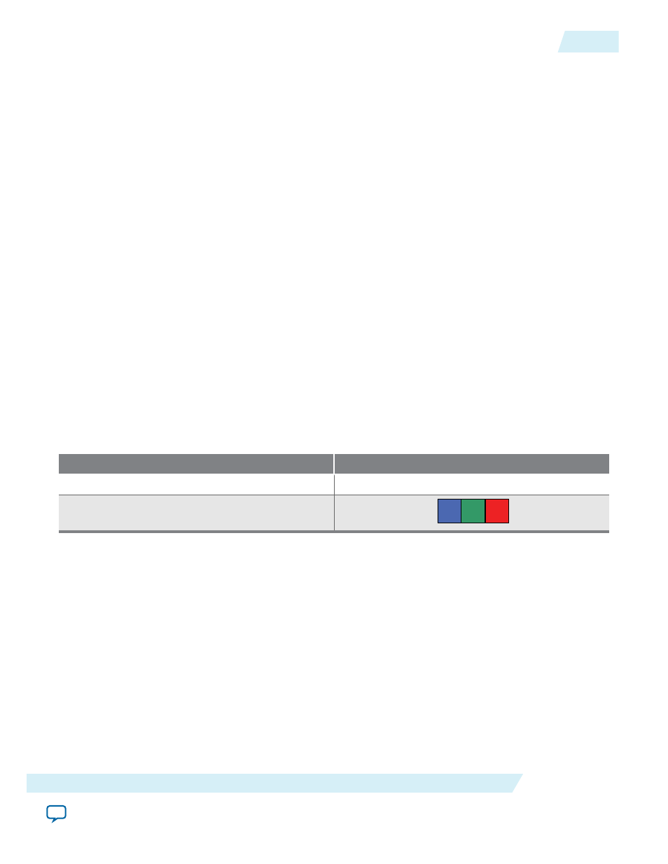
Table 2-11: Parameters for Example of Data Transferred in Sequence
The table below lists the bits per pixel per color plane and color pattern.
Parameter
Value
Bits per Color Sample
8
Color Pattern
R
G
B
UG-VIPSUITE
2015.05.04
Packet Transfer Examples
2-23
Interfaces
Altera Corporation