Trace system signals, Trace system signals -3 – Altera Video and Image Processing Suite User Manual
Page 255
Trace System Signals
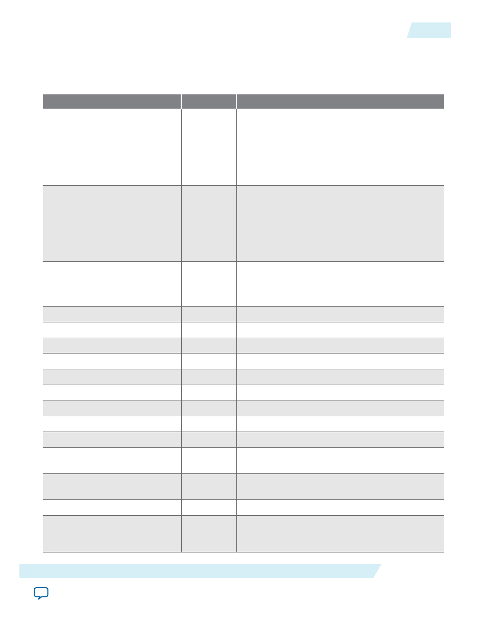
Table 20-2: Trace System Signals
Signal
Direction
Description
clk_clk
Input
All signals on the trace system are synchronous to this
clock.
Do not insert clock crossing between the monitor and
the trace system components. You must drive the
trace monitors’ clocks from the same source which
drives this signal.
reset_reset
Output
This signal is asserted when the IP core is being reset
by the debugging host. Connect this signal to the reset
inputs on the trace monitors.
Do not reset parts of the system being monitored with
this signal because this will interfere with function‐
ality of the system.
usb_if_clk
Input
Clock provided by On-Board USB-Blaster II.
All
usb_if
signals are synchronous to this clock; the
trace system provides clock crossing internally.
usb_if_reset_n
Input
Reset driven by On-Board USB-Blaster II.
usb_if_full
Output
Host to the target full signal.
usb_if_empty
Output
Target to the host empty signal.
usb_if_wr_n
Input
Write enable to the host to target FIFO.
usb_if_rd_n
Input
Read enable to the target to host FIFO.
usb_if_oe_n
Input
Output enable for data signals.
usb_if_data
Bidirectional Shared data bus.
usb_if_scl
Input
Management interface clock.
usb_if_sda
Input
Management interface data.
capturen_data
Input
capturen
port Avalon-ST
data
bus. This bus enables
the transfer of data out of the IP core.
capturen_endofpacket
Input
capturen
port Avalon-ST
endofpacket
signal. This
signal marks the end of an Avalon-ST packet.
capturen_empty
Input
capturen
port Avalon-ST
empty
signal.
capturen_ready
Output
capturen
port Avalon-ST
ready
signal. The
downstream device asserts this signal when it is able
to receive data.
UG-VIPSUITE
2015.05.04
Trace System Signals
20-3
Trace System IP Core
Altera Corporation