Altera Video and Image Processing Suite User Manual
Page 133
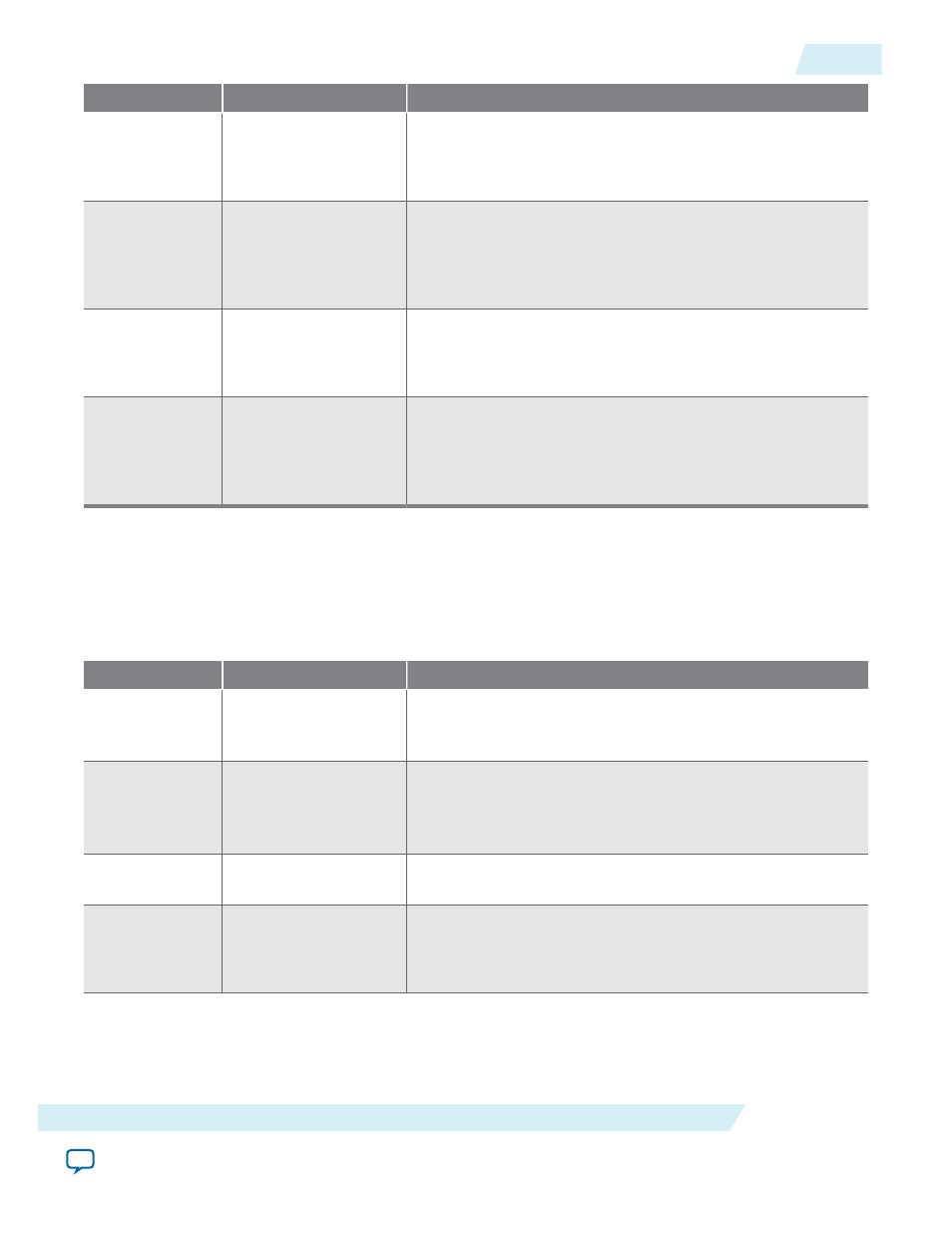
Address
Register
Description
2
Left Offset
The left offset, in pixels, of the clipping window/rectangle.
Note: The left and right offset values must be less than or
equal to the input image width.
3
Right Offset or
Width
In clipping window mode, the right offset of the window. In
clipping rectangle mode, the width of the rectangle.
Note: The left and right offset values must be less than or
equal to the input image width.
4
Top Offset
The top offset, in pixels, of the clipping window/rectangle.
Note: The top and bottom offset values must be less than
or equal to the input image height.
5
Bottom Offset or
Height
In clipping window mode, the bottom offset of the window. In
clipping rectangle mode, the height of the rectangle.
Note: The top and bottom offset values must be less than
or equal to the input image height.
Table 8-7: Clipper II Control Register Map
The control data is read once at the start of each frame and is buffered inside the IP core, so the registers can be
safely updated during the processing of a frame.
Note: The run-time control register map for the Clipper II IP core is altered and does not match the register map
of the Clipper IP core.
Address
Register
Description
0
Control
Bit 0 of this register is the
Go
bit, all other bits are unused.
Setting this bit to 0 causes the IP core to stop the next time
control information is read.
1
Status
Bit 0 of this register is the
Status
bit, all other bits are unused.
The Clipper IP core sets this address to 0 between frames. It is
set to 1 while the IP core is processing data and cannot be
stopped.
2
Interrupt
This bit is not used because the IP core does not generate any
interrupts.
3
Left Offset
The left offset, in pixels, of the clipping window/rectangle.
Note: The left and right offset values must be less than or
equal to the input image width.
UG-VIPSUITE
2015.05.04
Video Clipping Control Registers
8-7
Video Clipping IP Cores
Altera Corporation