Altera Video and Image Processing Suite User Manual
Page 63
• Clocked Video Input IP core
After reset, if the IP core has not yet determined the format of the incoming video, it uses the values
specified under the Avalon-ST Video Initial/Default Control Packet section in the parameter editor.
After determining an aspect of the incoming videos format, the IP core enters the value in the
respective register, sets the registers valid bit in the
Status
register, and triggers the respective
interrupts.
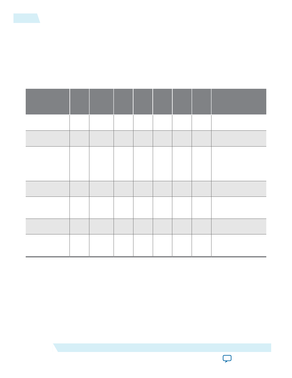
Table 4-4: Resolution Detection Sequence for a 1080i Incoming Video Stream
The table lists the sequence for a 1080i incoming video stream.
Status
Interru
pt
Active
Sample
Count
F0
Active
Line
Count
F1
Active
Line
Count
Total
Sample
Count
F0
Total
Sample
Count
F1
Total
Sample
Count
Description
00000000000
000
0
0
0
0
0
0
Start of incoming
video.
00000001000
000
1,920
0
0
2,200
0
0
End of first line of
video.
00100001000
100
1,920
0
0
2,200
0
0
Stable bit set and
interrupt fired —
Two of last three
lines had the same
sample count.
00100011000
100
1,920
540
0
2,200
563
0
End of first field of
video.
00110011000
100
1,920
540
0
2,200
563
0
Interlaced bit set—
Start of second field
of video.
00111011000
100
1,920
540
540
2,200
563
562
End of second field
of video.
10111011000
110
1,920
540
540
2,200
563
562
Resolution valid bit
set and interrupt
fired.
• Clocked Video Input II IP core
When the IP core detects a resolution, it uses the resolution to generate the Avalon-ST Video control
packets until a new resolution is detected. When the resolution valid bit in the
Status
register is 1, the
Active Sample Count
,
F0 Active Line Count
,
F1 Active Line Count
,
Total Sample Count
,
F0
Total Line Count
,
F1 Total Line Count
, and
Standard
registers are valid and contain readable
values. The interlaced bit of the
Status
register is also valid and can be read.
4-4
Clocked Video Input Format Detection
UG-VIPSUITE
2015.05.04
Altera Corporation
Clocked Video Interface IP Cores