Clocked video interface control registers, Clocked video interface control registers -36 – Altera Video and Image Processing Suite User Manual
Page 95
Signal
Direction
Description
vid_trs
Output
Clocked video time reference signal (TRS) signal. Used
with the SDI IP core to indicate a TRS, when asserted.
Note: For embedded synchronization mode only.
vid_v
Output
Clocked video vertical blanking signal. This signal is
asserted during the vertical blanking period of the video
stream.
Note: For separate synchronization mode only.
vid_v_sync
Output
Clocked video vertical synchronization signal. This signal
is asserted during the vertical synchronization period of
the video stream.
Note: For separate synchronization mode only.
Clocked Video Interface Control Registers
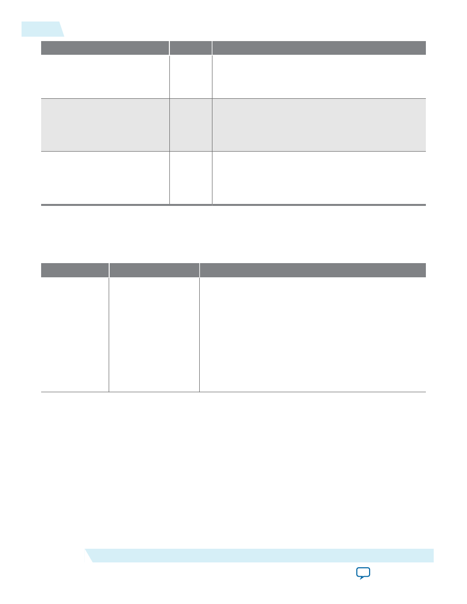
Table 4-20: Clocked Video Input Registers
Address
Register
Description
0
Control
• Bit 0 of this register is the
Go
bit:
• Setting this bit to 1 causes the CVI IP core start data
output on the next video frame boundary.
• Bits 3, 2, and 1 of the
Control
register are the interrupt
enables:
• Setting bit 1 to 1, enables the status update interrupt.
• Setting bit 2 to 1, enables the stable video interrupt.
• Setting bit 3 to 1, enables the synchronization outputs
(
sof
,
sof_locked
,
refclk_div
).
4-36
Clocked Video Interface Control Registers
UG-VIPSUITE
2015.05.04
Altera Corporation
Clocked Video Interface IP Cores