Using the control synchronizer ip core, Using the control synchronizer ip core -2 – Altera Video and Image Processing Suite User Manual
Page 154
Using the Control Synchronizer IP Core
The example illustrates how the Control Synchronizer IP Core is set to trigger on the changing of the
width field of control data packets.
In the following example, the Control Synchronizer IP Core is placed in a system containing the following
IP cores:
• Test Pattern Generator
• Frame Buffer
• Scaler II
The Control Synchronizer IP core must synchronize a change of the width of the generated video packets
with a change to the Scaler output size in the following conditions:
• The Scaler maintains a scaling ratio of 1:1 (no scaling)
• The Frame Buffer is configured to drop and repeat making it impossible to calculate packets streamed
into the frame buffer are streamed out to the Scaler.
• The Scaler cannot be configured in advance of a certain video data packet.
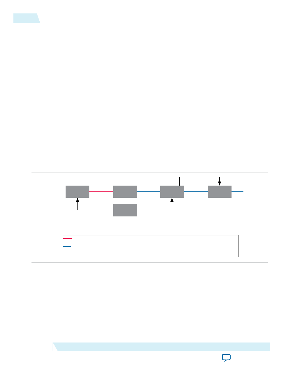
The Control Synchronizer IP Core solves the problem through the following sequence of events:
1. Sets up the change of video width.
Figure 11-1: Change of Video Width
Test Pattern
Generator
Frame
Buffer
Control
Synchronizer
Scaler
Nios II CPU
CPU Writes to
Test Pattern
Generator,
changing frame width to 320
Red Line Indicates Control Data Packet and Video Data Packet Pair Number 4 (Width 640)
Blue Line Indicates Control Data Packet and Video Data Packet Pair Number 0 (Width 640)
Control Data packet and Video Data Packet Pair Numbers 1, 2 and 3 are Stored in the Frame Buffer
CPU Writes to Control
Synchronizer, Configures it to
Change Scaler Output Size to 320 Width
When a Change in Width is Detected
Avalon MM
Avalon MM
Avalon MM
Avalon MM
Master
2. The Test Pattern Generator changes the size of its Video Data Packet and Control Data Packet pairs to
320 width. It is not known when this change will propagate through the Frame Buffer to the Scaler.
11-2
Using the Control Synchronizer IP Core
UG-VIPSUITE
2015.05.04
Altera Corporation
Control Synchronizer IP Core