Altera Video and Image Processing Suite User Manual
Page 73
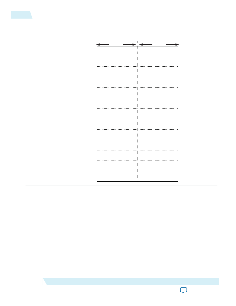
Figure 4-4: Ancillary Packet Register
The figure below shows the position of the ancillary packets. The different colors indicate different
ancillary packets.
2nd Data ID
Data ID
Data ID
Data Count = 7
Data Count = 5
User Word 1
User Word 2
User Word 3
User Word 4
User Word 2
User Word 4
User Word 6
0×FF
Ancillary Address
Ancillary Address +7
Ancillary Address +3
Ancillary Address +8
Ancillary Address +4
Ancillary Address +1
Ancillary Address +5
Ancillary Address +2
Ancillary Address +6
Ancillary Address +9
Ancillary Address +10
Ancillary Address +11
Ancillary Address +12
2nd Data ID
2nd Data ID
Data ID
Data Count = 4
User Word 2
User Word 1
User Word 3
User Word 4
User Word 5
User Word 1
User Word 3
User Word 5
User Word 7
Bits 15–8
Bits 7–0
Use the Depth of ancillary memory parameter to control the depth of the ancillary RAM. If available
space is insufficient for all the ancillary packets, then excess packets will be lost. The ancillary RAM is
filled from the lowest memory address to the highest during each vertical blanking period—the packets
from the previous blanking periods are overwritten. To avoid missing ancillary packets, the ancillary
RAM should be read every time the
End of field/frame interrupt
register triggers.
AFD Inserter (Clocked Video Output)
When the output of the AFD Inserter connects to the input of the CVO IP cores, the AFD Inserter inserts
an Avalon-ST Video ancillary data packet into the stream after each control packet. The AFD Inserter sets
the DID and SDID of the ancillary packet to make it an AFD packet (DID = 0x41, SDID = 0x5). The
contents of the ancillary packet are controlled by the AFD Inserter register map.
You can get the AFD Extractor from
.
4-14
Handling Ancillary Packets
UG-VIPSUITE
2015.05.04
Altera Corporation
Clocked Video Interface IP Cores