Frame reader control registers, Frame reader control registers -5 – Altera Video and Image Processing Suite User Manual
Page 196

Signal
Direction
Description
master_av_waitrequest
Input
master port Avalon-MM
waitrequest
signal. The system
interconnect fabric asserts this signal to cause the master
port to wait.
Frame Reader Control Registers
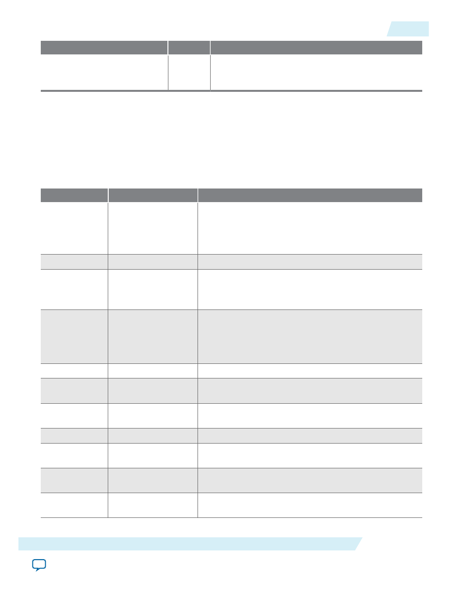
Table 13-3: Frame Reader Register Map
The control data is read once at the start of each frame and is buffered inside the IP core, so the registers can be
safely updated during the processing of a frame.
Note: The width of each register of the frame reader is 32 bits.
Address
Register
Description
0
Control
• Bit 0 of this register is the
Go
bit. Setting this bit to 1 causes
the IP core to start producing data.
• Bit 1 of this register is the interrupt enable. Setting this bit
to 1 enables the end of frame interrupt.
1
Status
Bit 0 of this register is the
Status
bit, all other bits are unused.
2
Interrupt
Bit 1 of this register is the end of frame interrupt bit, all other
bits are unused. Writing a 1 to bit 1 resets the end of frame
interrupt.
3
Frame Select
This register selects between frame 0 and frame 1 for next
output.
• Frame 0 is selected by writing a 0 here.
• Frame 1 is selected by writing a 1 here.
4
Frame 0 Base Address
The 32-bit base address of the frame.
5
Frame 0 Words
The number of words (reads from the master port) to read
from memory for the frame.
6
Frame 0 Single Cycle
Color Patterns
The number of single-cycle color patterns to read for the
frame.
7
Frame 0 Reserved
Reserved for future use.
8
Frame 0 Width
The width to be used for the control packet associated with
frame 0.
9
Frame 0 Height
The height to be used for the control packet associated with
frame 0.
10
Frame 0 Interlaced
The interlace nibble to be used for the control packet
associated with frame 0.
UG-VIPSUITE
2015.05.04
Frame Reader Control Registers
13-5
Frame Reader IP Core
Altera Corporation
