Altera Video and Image Processing Suite User Manual
Page 155
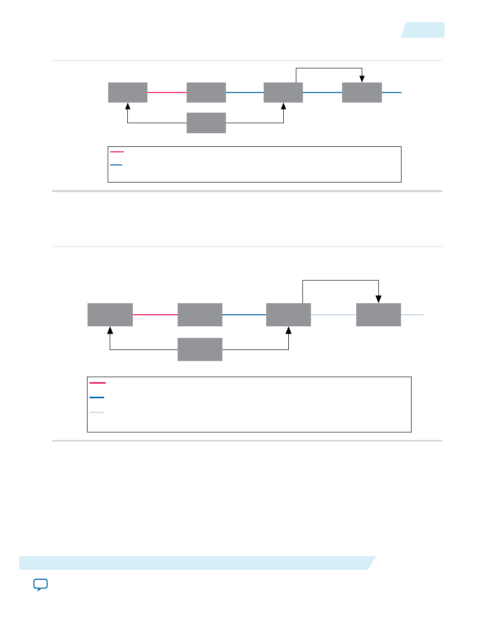
Figure 11-2: Changing Video Width
Test Pattern
Generator
Frame
Buffer
Control
Synchronizer
Scaler
Nios II CPU
Red Line Indicates Control Data Packet and Video Data Packet Pair Number 5 (Width 320)
Blue Line Indicates Control Data Packet and Video Data Packet Pair Number 1 (Width 640)
Control Data Packet and Video Data Packet Pair Numbers 2, 3, and 4 are Stored in the Frame Buffer
Avalon MM
Avalon MM
Avalon MM
Avalon MM
Master
3. The Video Data Packet and Control Data Packet pair with changed width of 320 propagates through
the Frame Buffer. The Control Synchronizer detects the change and triggers a write to the Scaler. The
Control Synchronizer stalls the video processing pipeline while it performs the write.
Figure 11-3: Test Pattern Generator Change
Test Pattern
Generator
Frame
Buffer
Control
Synchronizer
Scaler
Nios II CPU
Red Line Indicates Control Data Packet and Video Data Packet Pair Number 14 (Width 320)
Blue Line Indicates Control Data Packet and Video Data Packet Pair Number 5 (Width 320)
Light Blue Line Indicates Control Data Packet and Video Data Packet Pair Number 4 (Width 640)
Control Data Packet and Video Data Packet Pair Numbers 6 to 13 are Stored in the Frame Buffer
Control Synchronizer Writes the Data to the
Specified Addresses. This Configures the
Scaler to an Output Width of 320
Avalon MM
Avalon MM
Avalon MM
Avalon MM
Master
4. The Scaler is reconfigured to output width 320 frames. The Control Synchronizer resumes the video
processing pipeline. The scaling ratio maintains at 1:1.
UG-VIPSUITE
2015.05.04
Using the Control Synchronizer IP Core
11-3
Control Synchronizer IP Core
Altera Corporation