Video switching parameter settings, Video switching signals, Video switching parameter settings -3 – Altera Video and Image Processing Suite User Manual
Page 239: Video switching signals -3
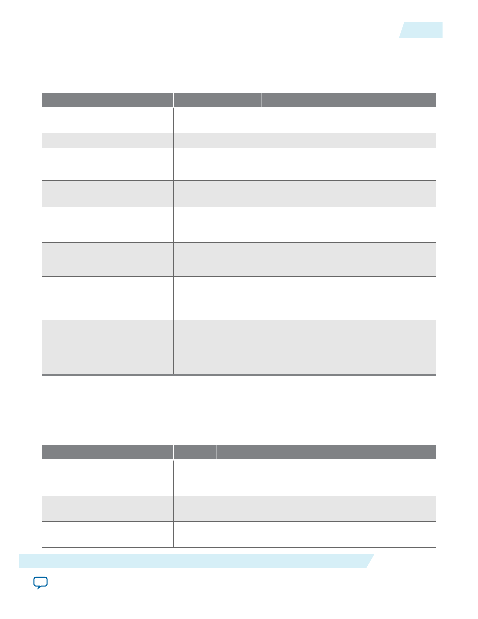
Video Switching Parameter Settings
Table 18-2: Video Switching Parameter Settings
Parameter
Value
Description
Bits per pixel per color plane
4–20, Default = 8
Select the number of bits per pixel (per color
plane).
Number of color planes
1–3, Default = 3
Select the number of color planes.
Color planes are in parallel
On or Off
• Turn on to set colors planes in parallel.
• Turn off to set colors planes in sequence.
Number of inputs
1–12, Default = 2
Select the number of Avalon-ST video inputs
to the IP core (
din
and
alpha_in
).
Number of outputs
1–12, Default = 2
Select the number of Avalon-ST video
outputs from the IP core(
dout
and
alpha_
out
).
Enable alpha channel
On or Off
Turn on to enable the alpha ports.
Note: Available only for Switch IP core.
Alpha bits per pixel
2, 4, 8
Select the number of bits used to represent
the alpha coefficient.
Note: Available only for Switch IP core.
Number of pixels in parallel
1, 2, or 4
Specify the number of pixels transmitted or
received in parallel.
Note: Available only for Switch II IP
core.
Video Switching Signals
Table 18-3: Video Switching Signals
The table below lists the signals for Switch and Switch II IP cores.
Signal
Direction
Description
reset
Input
The IP core asynchronously resets when you assert this
signal. You must deassert this signal synchronously to the
rising edge of the clock signal.
clock
Input
The main system clock. The IP core operates on the rising
edge of this signal.
din_N_data
Input
din_N
port Avalon-ST
data
bus. This bus enables the
transfer of pixel data into the IP core.
UG-VIPSUITE
2015.05.04
Video Switching Parameter Settings
18-3
Video Switching IP Cores
Altera Corporation