2d fir filter signals, 2d fir filter signals -4 – Altera Video and Image Processing Suite User Manual
Page 109
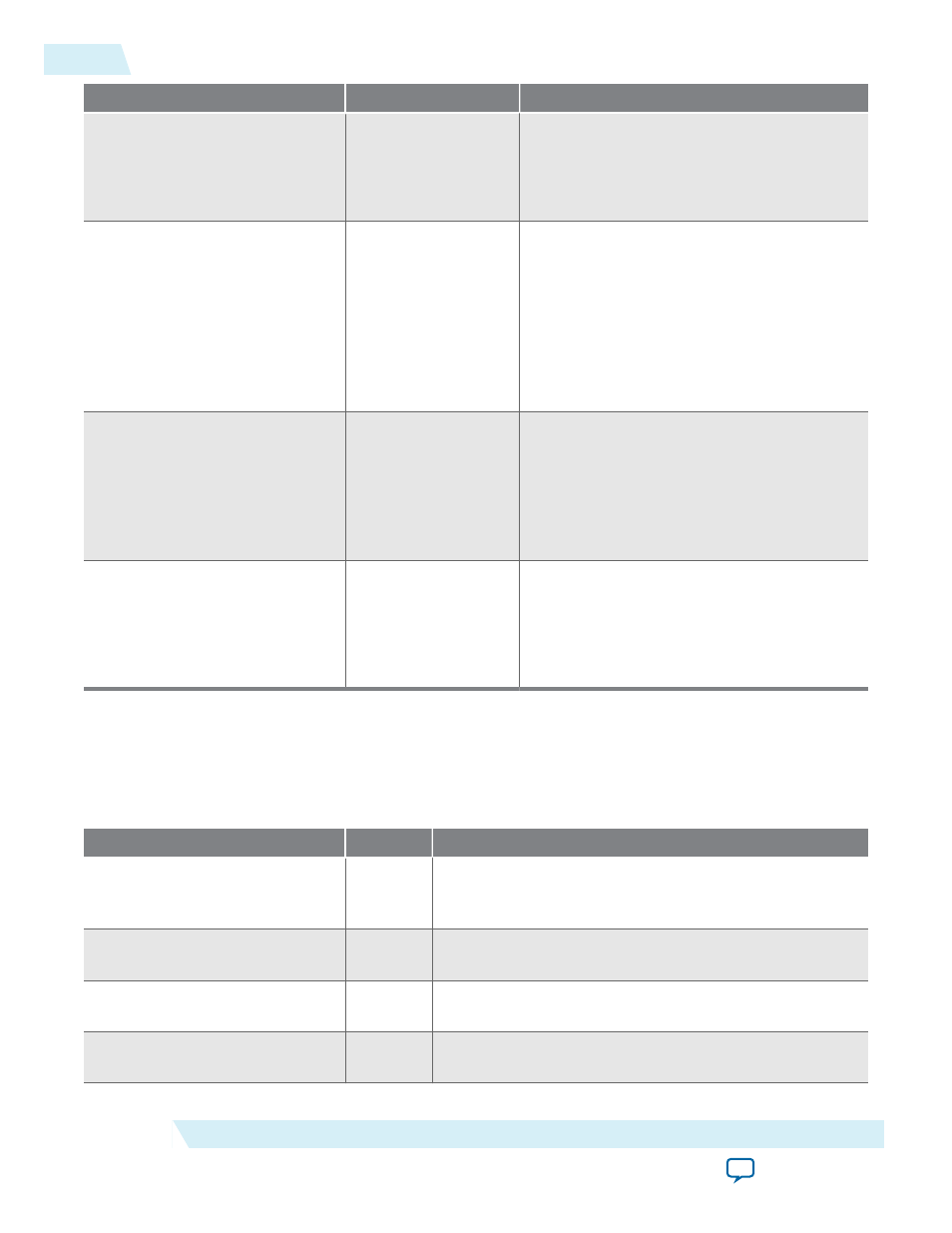
Parameter
Value
Description
Output data type: Min
1,048,575 to -524,288,
Default = 0
Set output range minimum value.
Note: The output is constrained to fall in
the specified range of maximum
and minimum guard band values.
Move binary point right
-16 to +16, Default = 0 Specify the number of places to move the
binary point. This can be useful if you require
a wider range output on an existing
coefficient set.
Note: You can specify a higher precision
output by increasing Bits per pixel
per color plane and Move binary
point right.
Remove fraction bits by
• Round values - Half
up
• Round values - Half
even
• Truncate values to
integer
Select the method to discard the fractional
bits resulting from the FIR calculation.
Convert from signed to unsigned
by
• Saturating to
minimum value at
stage 4
• Replacing negative
with absolute value
Select the method to convert the signed FIR
results to unsigned .
2D FIR Filter Signals
Table 5-2: 2D FIR Filter Signals
The table below lists the signals for 2D FIR Filter IP cores.
Signal
Direction
Description
reset
Input
The IP core asynchronously resets when you assert this
signal. You must deassert this signal synchronously to the
rising edge of the clock signal.
clock
Input
The main system clock. The IP core operates on the rising
edge of this signal.
din_data
Input
din_N
port Avalon-ST
data
bus. This bus enables the
transfer of pixel data into the IP core.
din_endofpacket
Input
din_N
port Avalon-ST
endofpacket
signal. This signal
marks the end of an Avalon-ST packet.
5-4
2D FIR Filter Signals
UG-VIPSUITE
2015.05.04
Altera Corporation
2D FIR Filter IP Core