Altera Video and Image Processing Suite User Manual
Page 45
Structure of a Control Data Packet
A control data packet complies with the standard of a packet type identifier followed by a data payload.
The data payload is split into nibbles of 4 bits; each data nibble is part of a symbol. If the width of a
symbol is greater than 4 bits, the function does not use the most significant bits of the symbol.
Order
Symbol
Order
Symbol
1
width[15..12]
6
height[11..8]
2
width[11..8]
7
height[7..4]
3
width[7..4]
8
height[3..0]
4
width[3..0]
9
interlacing[3..0]
5
height[15..12]
—
—
If the number of symbols transmitted in one cycle of the Avalon-ST interface is more than one, then the
nibbles are distributed such that the symbols occupying the least significant bits are populated first.
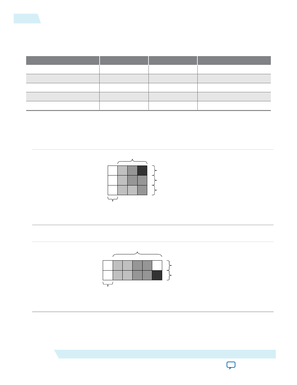
The following figures show examples of control data packets, and how they are split into symbols.
Figure 2-13: Three Symbols in Parallel
Start
End
3
15
Symbols in least significant bits
Symbols in middle significant bits
Symbols in most significant bits
Control data, reference numbers to Table 4-5
X
Control data packet type identifier
(4 bits in least significant symbol,
X’s for unused symbols)
X
9
6
8
5
2
7
4
1
Figure 2-14: Two Symbols in Parallel
Control data packet type identifier
(4 bits in least significant symbol,
X’s for unused symbols)
Symbols in least significant bits
Symbols in most significant bits
Start
End
Control data, reference numbers to Table 4-5
3
15
X
X
9
6
8
5
2
7
4
1
2-18
Control Data Packets
UG-VIPSUITE
2015.05.04
Altera Corporation
Interfaces