Altera Video and Image Processing Suite User Manual
Page 69
A CVI IP core can take in the locked PLL clock and the SOF signal and align the output video to these
signals. This produces an output video frame that is synchronized to the incoming video frame.
Clocked Video Input IP Core
For Clocked Video Input IP core, you can compare
vcoclk_div
to
refclk_div
, using a phase frequency
detector (PFD) that controls a voltage controlled oscillator (VCXO). By controlling the VCXO, the PFD
can align its output clock (
vcoclk
) to the reference clock (
refclk
). By tracking changes in the
refclk_div
signal, the PFD can then ensure that the output clock is locked to the incoming video clock.
You can set the SOF signal to any position within the incoming video frame. The registers used to
configure the SOF signal are measured from the rising edge of the F0 vertical sync. Due to registering
inside the settings of the CVI IP cores, the SOF Sample and SOF Line registers to 0 results in a SOF signal
rising edge:
• six cycles after the rising edge of the V sync in embedded synchronization mode
• three cycles after the rising edge of the V sync in separate synchronization mode
A rising edge on the SOF signal (0 to 1) indicates the start of frame.
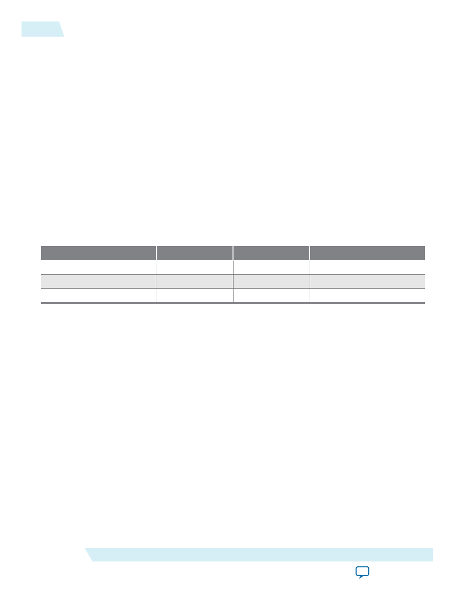
Table 4-6: Example of Clocked Video Input To Output an SOF Signal
The table below list an example of how to set up the Clocked Video Input IP core to output an SOF signal aligned
to the incoming video synchronization (in embedded synchronization mode).
Format
SOF Sample Register
SOF Line Register
Refclk Divider Register
720p60
1644 << 2
749
1649
1080i60
2194 << 2
1124
2199
NTSC
856 << 2
524
857
4-10
Generator Lock
UG-VIPSUITE
2015.05.04
Altera Corporation
Clocked Video Interface IP Cores