Control synchronizer parameter settings, Control synchronizer parameter settings -4 – Altera Video and Image Processing Suite User Manual
Page 156
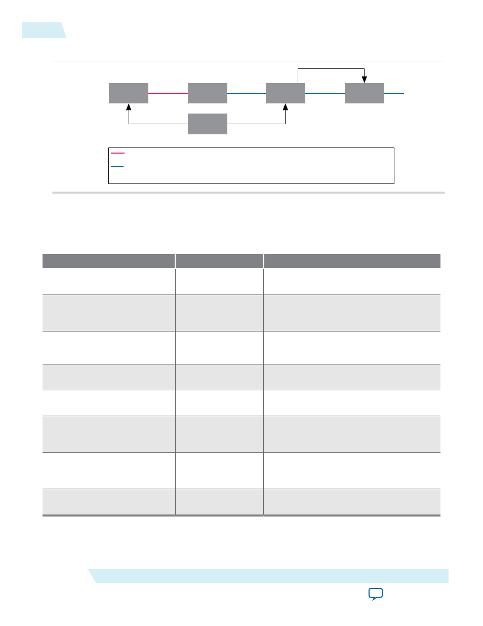
Figure 11-4: Reconfigured Scaler II
Test Pattern
Generator
Frame
Buffer
Control
Synchronizer
Scaler
Nios II CPU
Red Line Indicates Control Data Packet and Video Data Packet Pair Number 14 (Width 320)
Blue Line Indicates Control Data Packet and Video Data Packet Pair Number 5 (Width 320)
Control Data Packet and Video Data Packet Pair Numbers 6 to 13 are Stored in the Frame Buffer
Avalon MM
Avalon MM
Avalon MM
Avalon MM
Master
Control Synchronizer Parameter Settings
Table 11-1: Control Synchronizer Parameter Settings
Parameter
Value
Description
Bits per pixel per color plane
4-20, Default = 8
Select the number of bits per pixel (per color
plane).
Number of color planes
1–4, Default = 3
Select the number of color planes that are
sent over one data connection. For example, a
value of 3 for R'G'B' R'G'B' R'G'B' in serial.
Color planes are in parallel
On or Off
• Turn on to set colors planes in parallel.
• Turn off to set colors planes in series.
Trigger on width change
On or Off
Turn on to start transfer of control data when
there is a change in width value.
Trigger on height change
On or Off
Turn on to start transfer of control data when
there is a change in height value.
Trigger on start of video data
packet
On or Off
Turn on to start transfer of control data when
the core receives the start of video data
packet.
Require trigger reset via control
port
On or Off
Turn on to disable the trigger once triggered.
If you turn on this parameter, you need to
enable the trigger using the control port.
Maximum number of control
data entries
1–10, Default = 3
Specify the maximum number of control data
entries that can be written to other cores.
11-4
Control Synchronizer Parameter Settings
UG-VIPSUITE
2015.05.04
Altera Corporation
Control Synchronizer IP Core