Deinterlacing control registers, Deinterlacing control registers -23 – Altera Video and Image Processing Suite User Manual
Page 182
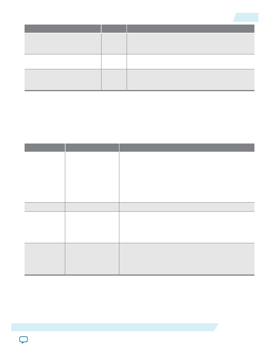
Signal
Direction
Description
motion_write_master_
burstcount
Output
motion_write_master
port Avalon-MM
burstcount
signal. This signal specifies the number of transfers in each
burst.
motion_write_master_
writedata
Output
motion_write_master
port Avalon-MM
writedata
bus.
These output lines carry data for write transfers.
motion_write_master_
waitrequest
Input
motion_write_master
port Avalon-MM
waitrequest
signal. The system interconnect fabric asserts this signal to
cause the master port to wait.
Deinterlacing Control Registers
Table 12-8: Deinterlacer Control Register Map for Run-Time Control of the Motion-Adaptive Algorithm
The table below describes the control register map that controls the motion-adaptive algorithm at run time. The
control data is read once and registered before outputting a frame. It can be safely updated during the processing
of a frame.
Address
Register
Description
0
Control
Bit 0 of this register is the
Go
bit, all other bits are unused.
• Setting this bit to 0 causes Deinterlacer IP core to stop
before control information is read and before producing a
frame.
• While stopped, the Deinterlacer IP core may continue to
receive and drop frames at its input if triple-buffering is
enabled.
1
Status
Bit 0 of this register is the
Status
bit, all other bits are unused.
2
Motion value
override
Write-only register.
Bit 0 of this register must be set to 1 to override the per-pixel
motion value computed by the deinterlacing algorithm with a
user specified value. This register cannot be read.
3
Blending coefficient
Write-only register.
The 16-bit value that overrides the motion value computed by
the deinterlacing algorithm. This value can vary between 0
(weaving) to 65535 (bobbing). The register cannot be read.
UG-VIPSUITE
2015.05.04
Deinterlacing Control Registers
12-23
Deinterlacing IP Cores
Altera Corporation