Underflow and overflow, Underflow and overflow -11 – Altera Video and Image Processing Suite User Manual
Page 70
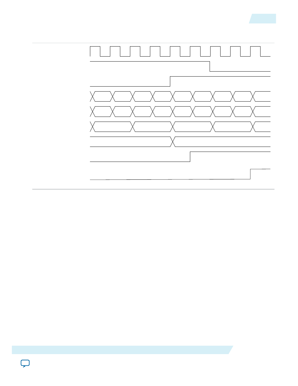
Figure 4-3: Genlock Example Configuration
The figure shows an example of a Genlock configuration for Clocked Video Input IP core.
524
0
0
1
0
1
1
0
1
0
SubSample
0
2
0
1
Sample
Cb
Y
Cr
Y
Y
Cr
Y
Cb
Cb
856
857
V Sync
Data
Line
SOF
(SOFSubSample = 0,
SOFSample = 0, SOFLine = 0)
F
SOF
(SOFSubSample = 1,
SOFSample = 1, SOFLine = 1)
Clocked Video Input II IP Core
For Clocked Video Input II IP core, the SOF signal produces a pulse on the rising edge of the V sync. For
interlaced video, the pulse is only produced on the rising edge of the F0 field, not the F1 field. A start of
frame is indicated by a rising edge on the SOF signal (0 to 1).
Underflow and Overflow
Moving between the domain of clocked video and the flow controlled world of Avalon-ST Video can
cause flow problems. The Clocked Video Interface IP cores contain a FIFO can accommodate any bursts
in the flow data when set to a large enough value. The FIFO can accommodate any bursts as long as the
input/output rate of the upstream/downstream Avalon-ST Video components is equal to or higher than
that of the incoming/outgoing clocked video.
Underflow
The FIFO can accommodate any bursts as long as the output rate of the downstream Avalon-ST Video
components is equal to or higher than that of the outgoing clocked video. If this is not the case, the FIFO
underflows. If underflow occurs, the CVO IP cores continue to produce video and resynchronizing the
startofpacket
for the next image packet, from the Avalon-ST Video interface with the start of the next
frame. You can detect the underflow by looking at bit 2 of the
Status
register. This bit is sticky and if an
underflow occurs, it stays at 1 until the bit is cleared by writing a 1 to it.
UG-VIPSUITE
2015.05.04
Underflow and Overflow
4-11
Clocked Video Interface IP Cores
Altera Corporation