Example 1-rung ladder logic program – Rockwell Automation 9323-PA1E USER MANUAL APS 6.0 User Manual
Page 57
Ladder Logic Program Basics
4–3
Example 1-Rung Ladder Logic Program
A ladder logic program consists of individual rungs, each containing at least one
output instruction and one or more input instructions. The ladder rung that follows
has two input instructions and an output instruction. An output instruction always
appears at the right, next to the right power rail. Input instructions always appear to
the left of the output instruction.
A simple rung, using relay logic instructions
XIC
( )
B3
12
] [
B3
10
]/[
B3
11
XIO
OTE
Input Instructions
Output Instruction
XIC = Examine if Closed
XIO = Examine if Open
OTE = Output Energize
Address B3/10
Address B3/11
Address B3/12
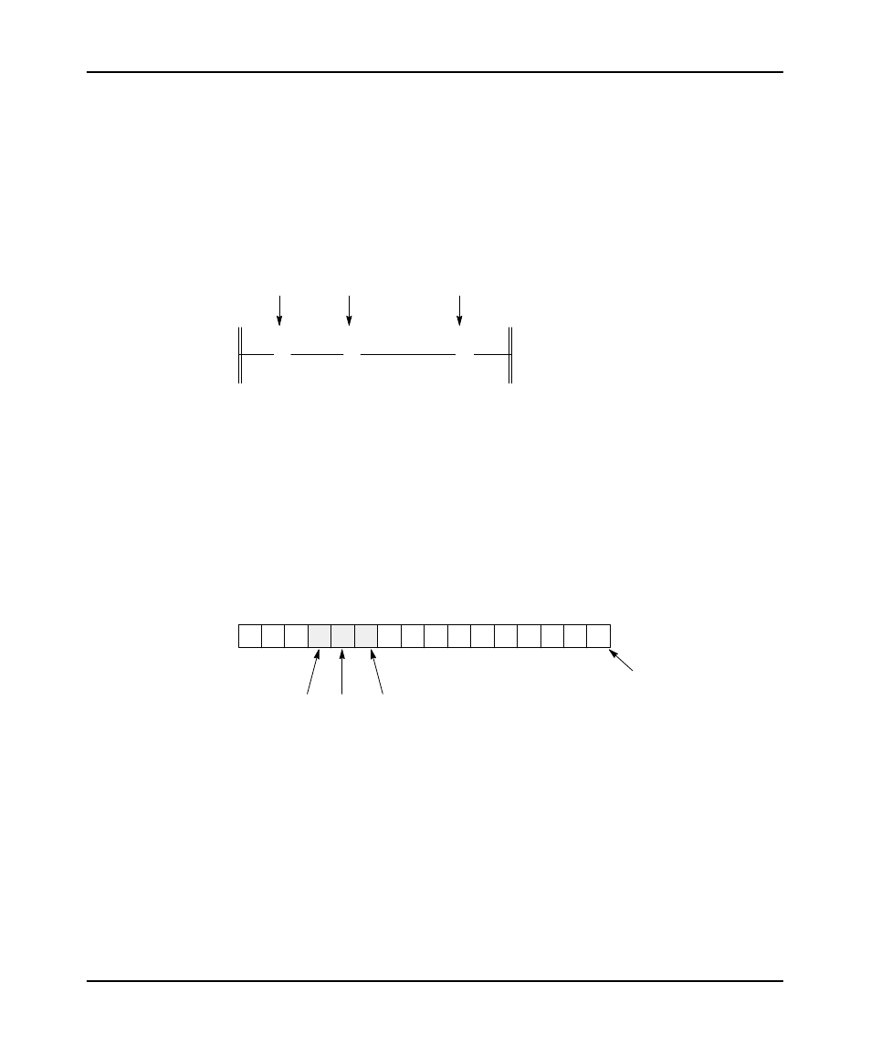
Note that each instruction in the diagram above has an address. This address
identifies a location in the processor’s data files, where the on/off state of the bit is
stored. Addresses of the above instructions indicate Bit data file 3 (B3), bits 10, 11,
and 12:
OTE
XIC
XIO
Bit Data File 3
Ć Element 0
Bit Status
0 0 0 1 0 1 0 0 0 0 0 0 0 0 0 0
15 14 13 12 11 10 9 8 7 6 5 4 3 2 1 0
In the preceding diagram, we indicated that bit 10 is logic 1 (On), bit 11 is logic 0
(Off), and bit 12 is logic 1 (On). These logic states indicate whether an instruction
is true or false, as pointed out in the following table.