Rockwell Automation 9323-PA1E USER MANUAL APS 6.0 User Manual
Page 205
Configuring Your Programming Device for Online Communication
11–11
1784-KT (DH
+
Bridged) and 1784-KT2 (DH
+
Bridged) Interface Cards
The 1784-KT (DH
+
Bridged) or the 1784-KT2 (DH
+
Bridged) interface cards
require a 1785-KA5 DH
+
/DH-485 gateway module to bridge the DH
+
and DH-485
data links when communicating from a terminal located on a DH
+
data link.
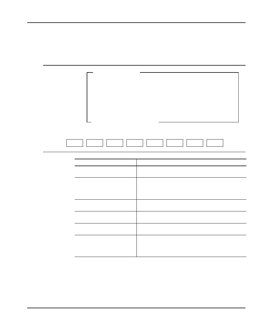
Current Device
1784-KT (DH+ Bridged)
F3
Connection
DIRECT
F4
Terminal DH
+
Address
0 (octal)
F5
SLC Node Address
1 (decimal)
F6
KA5 DH
+
Address
1 (octal)
F7
IRQ
3
F8
Board Address
000011
F9
Save to File
F9
Press a function key
SAVE T0
FILE
F5
F6
SLC
ADDRESS
KA5
ADDRESS
F3
CONNECT
TYPE
F2
SELECT
DEVICE
F4
TERM
ADDRESS
ESC exits/Alt-U aborts changes
ONLINE CONFIGURATION
F7
IRQ
F8
BOARD
ADDRESS
Function Key
Description
[F2] Select Device
Toggles between the selected interface card and the interface
card selection menu.
[F3] Connect Type
Toggles between Direct and MultiĆDrop. Direct means that the
terminal has a termination resistor (last device on the DH
+
link). MultiĆDrop means that the terminal does not have a
termination resistor. The default is Direct.
[F4] Terminal Address
➀
Allows you to select a terminal address on DH+ as a node
number from 0–77 octal. The default is 0.
[F5] SLC Address
Allows you to select a processor address on DHĆ485 as a
node number from 1–31 decimal. The default is 1.
[F6] KA5 Address
➀
Allows you to select a KA5 address on DH
+
as a node number
from 0–77 octal. The default is 1.
[F7] IRQ
Allows you to select the IRQ on the board (3, 4, 5, and 7.) The
software default is 3. This selection must match the setting of
the jumpers on your KT(2) card (hardware default is 0). See
the KT(2) card user manual for details..