Evaluating how processor memory is stored, Preface, Data table map – Rockwell Automation 9323-PA1E USER MANUAL APS 6.0 User Manual
Page 171
Preface
Advanced Programming Software User Manual
9–8
Evaluating How Processor Memory is Stored
Once you have successfully saved and compiled your processor file, you may view
how that file is stored in memory.
The short-cut
[ALT–M]
allows you to access the Data Table Map and Processor
Memory Layout more quickly from the Program Directory display.
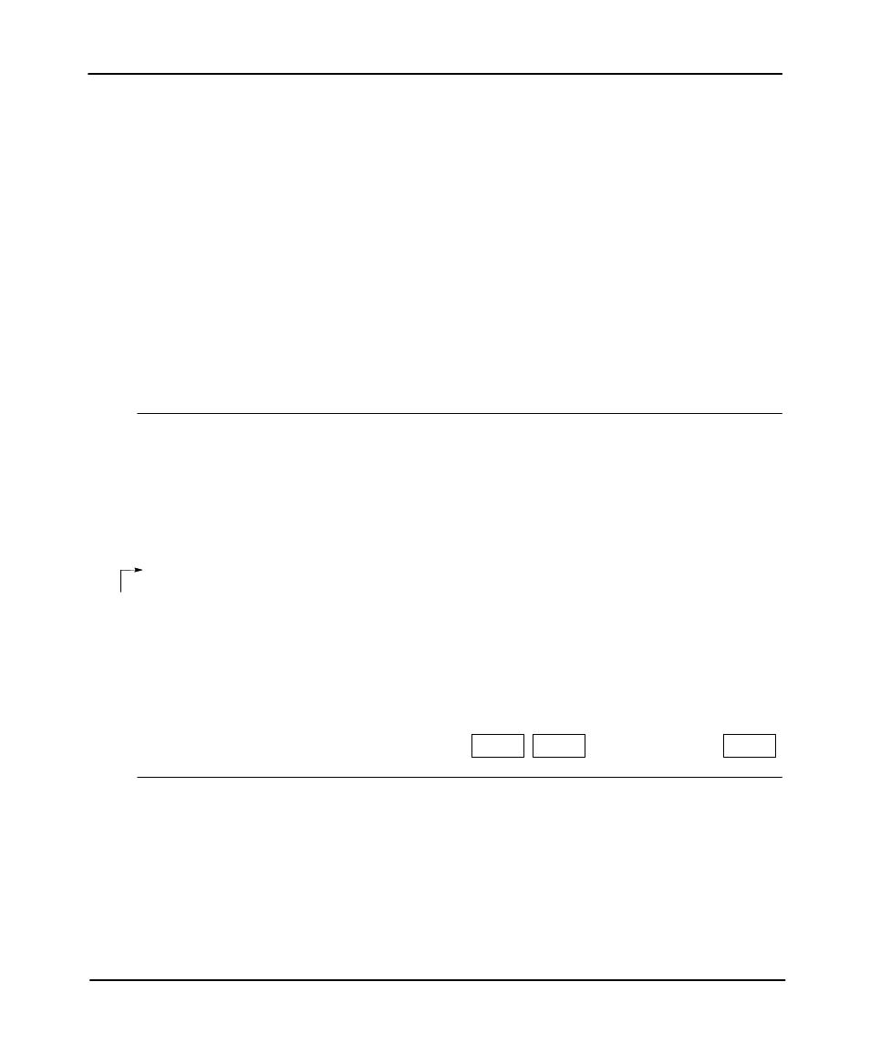
Data Table Map
This function lists the data files created by the I/O configuration and ladder
program. It also lists the default bit, timer, counter, control, integer, and floating
point files, 3 through 8. Additional files (9-255) can be created if needed using
[F6], Create Data File. Refer to chapter 6 regarding how to create data files.
FILE
TYPE
LAST ADDRESS
ELEMENTS WORDS
FILE PROTECTION
0
O output
O:2
1
1
1
I input
I:3
2
2
STATIC
2
S status
S:82
83
83
3
B binary or bit
B3/15
1
1
4
T timer
T4:10
11
33
5
C counter
C5:10
11
33
6
R control
R6:10
11
33
7
N integer
N7:255
256
256
8
F floating
F8:0
1
2
PROCESSOR MEMORY LAYOUT
444 data words of memory used in 9 data table files
266 instruction words of memory used in 3 program files
11924 instruction words of unused memory available
Press a key or enter file number
offline
SLC 5/03
File EXAMPLE
DATA TABLE MAP
File 8 only applies to
SLC 5/03 OS301,
OS302 and SLC 5/04
OS400, OS401
processors.
F10
DATA
PROTECT
F6
CREATE
DT FILE
F7
DELETE
DT FILE