Fluke Biomedical 601PRO XL User Manual
Page 123
S T A N D A R D S A N D P R I N C I P L E S
8 - 9
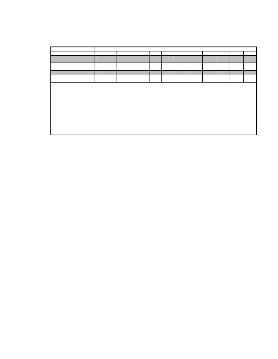
IEC 601-1 Conventional Test Sequence and Test Limits for Auto and Step Tests (Continued)
IEC 601-1 STANDARD
CLASS I
CLASS II
CLASS IP
DESCRIPTION
POLARITY
CIRCUIT B BF CF B BF CF B BF CF
Power Off Delay
Reverse
No L2
N/A
N/A
N/A
Patient Auxiliary --
µA DC
Only
Reverse No
L2 50 50 50 50 50 50 NT NT NT
Startup Delay
Reverse
No E
N/A
N/A
N/A
N/A
N/A
N/A
Patient Auxiliary --
µA DC
Only
Reverse No
E 50 50 50 NT NT NT NT NT NT
*This test takes one minute in Step mode.
**The limit for Protective Earth Resistance is dependent upon the device under test: 0.2
Ω
for devices with a non-detachable power
supply cord; 0.1
Ω
for devices with an appliance inlet.
***Limits for Insulation Resistance are not specified in IEC 601-1.
****Patient Leakage Current, Mains on Applied Part -- Normal Outlet is performed with NORMAL OUTLET polarity and both Normal and
Reversed phase isolated 110% of mains. Patient Leakage Current, Mains on Applied Part -- Reversed Outlet is performed in the same
manner as with a normal outlet except with REVERSE OUTLET polarity.
The limits have been removed for the Enclosure Leakage test with Class IP due to the fact that zero readings are always expected.
Delays are not applied to Class IP sequences.