Edwards Signaling eFSA250 User Manual
Page 38
Chapter 1: Installation and wiring
26
E-FSA64 and E-FSA250 Technical Reference Manual
Requirements
When connecting a CTM to the panel, the following hardware and programming
requirements must be met:
• The CTM must be connected to either a panel NAC, or a NAC module
• The NAC used must be dedicated to CTM use only
• All alarm points or zones (if programmed as a zoned system) must be
programmed to activate the dedicated NAC
• The NAC used must be programmed as City Tie
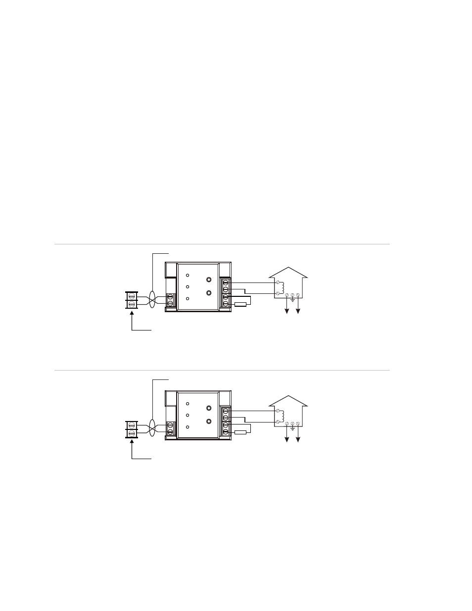
Wiring
The following wiring diagrams show how the polarity switches during an alarm
condition.
Figure 37: CTM module wiring (panel in normal condition)
Notification
appliance circuit
1
1
2
2
CTM
+
+
+
+
_
_
_
_
[1] [2]
Master box
Normal condition
[3]
[4]
[5]
[6]
Public fire alarm
reporting system
3
4
Figure 38: CTM module wiring (panel in alarm condition)
Notification
appliance circuit
1
1
2
2
CTM
+
+
+
+
_
_
_
_
[1] [2]
Master box
Public fire alarm
reporting system
Alarm condition
[3]
[4]
[5]
[6]
3
4
[1] 200 mA into a 14.5 Ω trip coil max. loop
resistance = 25 Ω
[2] This circuit is nonpower-limited and is
supervised for grounds and opens, but
not shorts
[3] Supervised and power-limited
[4] NAC must be programmed for city tie
[5] CTM must be mounted in the same room
as the panel
[6] 15 kΩ end-of-line resistor