Edwards Signaling eFSA250 User Manual
Page 235
Appendix B: Worksheets
E-FSA64 and E-FSA250 Technical Reference Manual
223
Step 2: Longest path
Use the tables that follow to determine the device loop’s longest circuit path. The
longest circuit path is based on wire size and type, and the number of detectors,
modules, E-2WIREs installed on the loop. The distances listed are for devices
that are evenly distributed on the loop. Please contact your distributor for loop
wire distances for devices on an end-loaded loop.
Note:
When using the tables to calculate a wire length for the eFSA64 panel, do
not exceed a total of 64 device addresses (any combination of detectors and
modules).
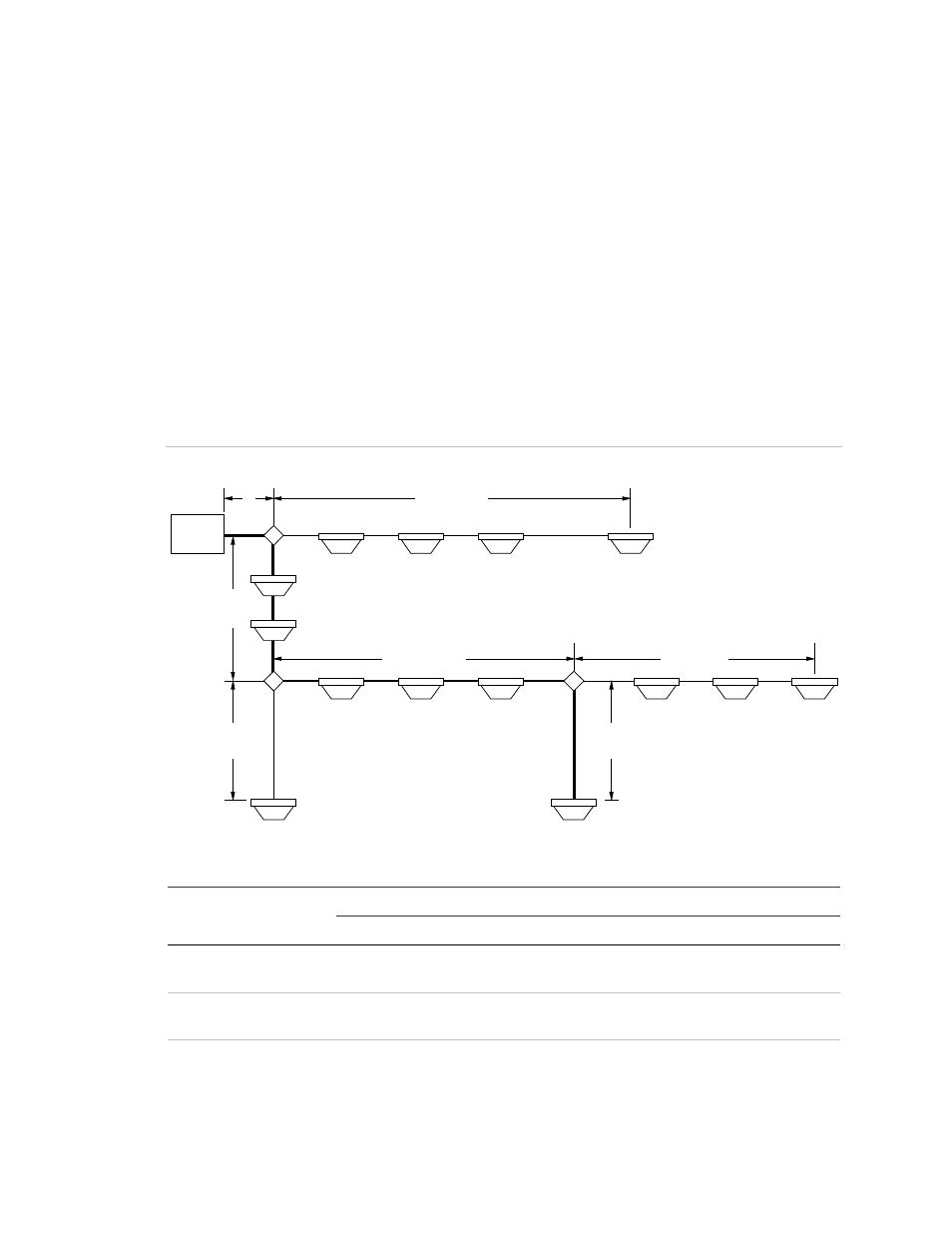
In the illustration below, the longest circuit path (shown in bold lines) is 1,240 ft.
(378 m). The total amount of wire comprising the loop is 1,640 ft. (500 m).
Figure 56: Device circuit path diagram
FACP
J
J
10 ft
(3 m)
200 ft
(61 m)
30 ft
(9 m)
J
100 ft
(30 m)
1000 ft
(305 m)
200 ft
(61 m)
100 ft
(30 m)
Table 50: Twisted shielded and nontwisted shielded
Evenly distributed distance
End-loaded distance
Sensors
Modules 18 AWG 16 AWG 14 AWG 18 AWG 16 AWG 14 AWG
127
0
5172 ft.
(1576 m)
6098 ft.
(1858 m)
5952 ft.
(1814 m)
5172 ft.
(1576 m)
6098 ft.
(1858 m)
5952 ft.
(1814 m)
120
7
5172 ft.
(1576 m)
6098 ft.
(1858 m)
5952 ft.
(1814 m)
5172 ft.
(1576 m)
6098 ft.
(1858 m)
5952 ft.
(1814 m)
115
12
5172 ft.
(1576 m)
6098 ft.
(1858 m)
5952 ft.
(1814 m)
5172 ft.
(1576 m)
6098 ft.
(1858 m)
5952 ft.
(1814 m)