Edwards Signaling eFSA250 User Manual
Page 29
Chapter 1: Installation and wiring
E-FSA64 and E-FSA250 Technical Reference Manual
17
Circuit specifications
• Circuit voltage range: 21.9 to 28.3 V
• AUX 1 + AUX 2 can supply 1.5 A total. If more than 1.5 A is required, you
must use a power-limited and regulated 24 VDC auxiliary/booster power
supply that is UL/ULC and FM Listed (if the installation requires FM
regulation) for fire protective signaling systems.
• For a complete list of auxiliary/booster power supplies, refer to the VS1 and
VS2 Series Compatibility List (P/N 3101065). Also refer to the Technical
Reference Manual (P/N 387515) for a list of compatible power supplies, if
you need to power GSA-REL module.• Continuous circuit (AUX power 1): 24
VDC nominal at 500 mA. Use this circuit to supply 24 VDC continuous power.
• Resettable circuit (AUX power 2): 24 VDC nominal at 500 mA (1 A possible if
you reduce total available NAC power by 500 mA). Use this circuit to provide
24 VDC resettable power. You can configure AUX power 2 as a continuous
circuit if you do not need a resettable circuit.
• Special application circuits
• Ground fault impedance: 0 to 5 kΩ
• Supervised and power-limited
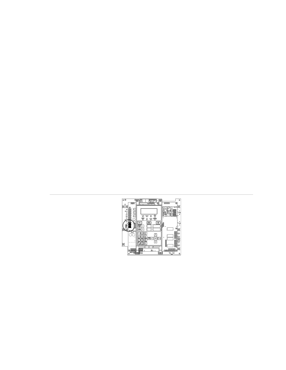
Figure 24: Auxiliary/smoke power wiring location