Control panel testing – Edwards Signaling eFSA250 User Manual
Page 209
Chapter 5: Diagnostics, maintenance, and testing
E-FSA64 and E-FSA250 Technical Reference Manual
197
continue with the next step.
— or —
Choose “Back” to return to the Diagnostics menu.
If you choose Back, you have to go to the Reports
menu > Diagnostics > Loop Comm Check to see
the report once the report is created.
Note:
This process may take considerable time
depending on how large the system is. If it takes
longer than four minutes (logon time expiration),
the system automatically logs you off if there is no
activity. Should this occur, you must log on again
and go to the Reports section to view the
diagnostic report, once it is generated.
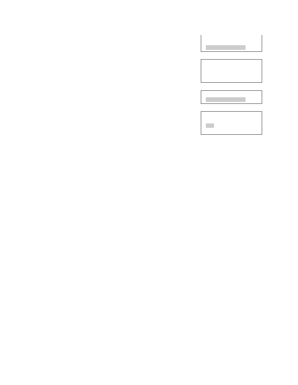
5. Choose Loop Comm Check.
6. Choose either:
LCD: This displays the report on the LCD.
— or —
Printer: The sends the report the printer (if one is
connected to the panel). If you do not have a
printer, this option is not available.
7. If you selected LCD, press Cancel twice to return
to the reports menu, when you have finished
viewing the report.
8. Press the Menu button to exit menu mode.
Recalibrate Device
Flash Device LED
Loop Comm Check
Diagnostics
Executing
#######
<-Continue <-Back
Diagnostics
Loop Comm Check
Loop Comm Check
LCD
Printer
Control panel testing
Before starting, notify all areas where the alarm sounds and off-premises
locations that receive alarm and trouble transmissions that testing is in progress.
Records of all testing and maintenance shall be kept as required by the AHJ.
• Required tools:
Slotted screwdriver, insulated
Digital multimeter
12 in. (30.5 cm) jumper lead with alligator clips
Panel door key
Sound level meter