Panel electronics installation – Edwards Signaling eFSA250 User Manual
Page 15
Chapter 1: Installation and wiring
E-FSA64 and E-FSA250 Technical Reference Manual
3
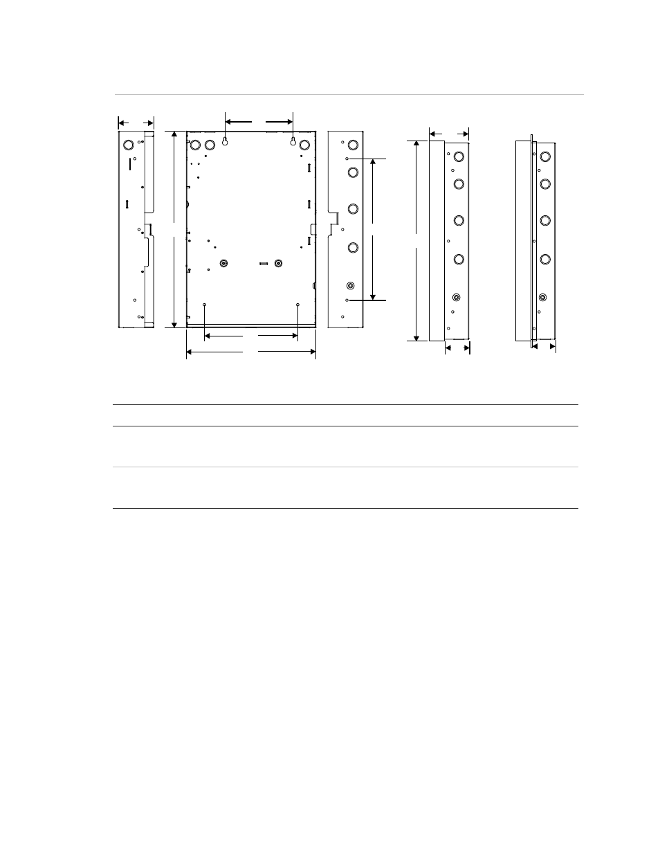
Figure 2: Panel backbox, backbox with door, and backbox with door and trim ring attached
D1
D2
D3
D4
D5
D6
Surface mounting holes
S
em
ifl
us
h
m
ou
nt
in
g
ho
le
s
Surface mounting holes
D8
D7
D9
Backbox with
door attached
Backbox with door and
trim ring attached
D9
Table 2: Backbox and backbox with door dimensions (in. and cm)
Model
D1 [1] D2
D3
D4
D5 [1] D6
D7
D8
D9
eFSA64
21.50
(54.6)
3.85
(9.8)
7.5
(19)
15.50
(39.4)
14.25
(36.2)
10.25
(26.0)
3.9
(9.9)
21.7
(55.1)
2.7
(6.8)
eFSA250
28.0
(71.1)
3.85
(9.8)
9.0
(22.8)
22.0
(55.8)
15.75
(40.0)
10.25
(26.0)
3.9
(9.9)
28.2
(71.6)
2.7
(6.8)
[1] Add 1-1/2 in. (3.81 cm) to D1 and D5 dimensions for trim kit. The trim kit provides .75 inches
(1.9 cm) of trim to the top, bottom, and sides of the panel backbox.
Panel electronics installation
To reduce possible damage to the panel’s electronics during backbox installation,
the electronics are packaged separately and must be installed in the panel
backbox. The electronics are shipped already mounted to a plastic backplane.
Note:
Be sure that any possibility for construction damage and vandalism has
passed before installing the panel electronics.