Edwards Signaling Genesis Ceiling Strobe User Manual
Genesis ceiling strobe, Product information, Specifications
Installation Sheet
29APR05
P/N: 3100612 REV: 3.0
Genesis Ceiling Strobe
1 / 2
Genesis Ceiling Strobe
Product information
The Genesis Ceiling Strobe is a visible fire alarm notification
appliance designed for indoor ceilings and walls. See Table 1
for a list of model numbers.
The strobe includes a field configurable switch for selecting the
desired candela output. The candela output setting is locked in
place and remains visible after final installation.
This strobe features an enhanced synchronization circuit to
comply with the latest requirements of UL 1971 Signaling
Devices for the Hearing Impaired and the latest Canadian
standard CAN/ULC S526-02. Synchronized operation requires
a separately installed synchronization control module. See
Table 2 for a list of compatible synchronization modules.
Install this device in accordance with applicable requirements
in the latest editions of the NFPA codes and standards and
Canadian Electrical Code, Part 1, Section 32, CAN/ULC S524-
01, Standard for the Installation of Fire Alarm Systems, and in
accordance with the local authorities having jurisdiction.
Table 1: Models
Description Number
Strobe,
15 to 95 multi-cd, white
ADTGC-VM
MGC-VM
EGC-VM
XLSGC-VM
GC-VM
ZGC-VM
GC-VM-LG
Strobe,
15 to 95 multi-cd, white,
with FIRE marking
ADTGCF-VM
MGCF-VM
EGCF-VM
XLSGCF-VM
GCF-VM
ZGCF-VM
GCF-VM-LG
Strobe,
15 to 95 multi-cd, red,
with FIRE marking
EGCFR-VM
GCFR-VM
MGCFR-VM
Table 2: Compatible synchronization modules
Description Model
number
Auto-Sync Output
Module
SIGA-CC1S SIGA-MCC1S
SIGA-CC1S-LG SIGA-MCC1S-LG
Genesis Signal Master -
Remote Mount
ADTG1M-RM MG1M-RM
EG1M-RM XLSG1M-RM
G1M-RM ZG1M-RM
G1M-RM-LG
Specifications
Operating voltage
Regulated 16 to 33 Vdc, 16 to 33 Vfwr
This device was tested to the Regulated 24 Vdc/fwr
operating voltage limits of 16 V and 33 V. Do not apply
80% and 110% of these values for system operation.
Strobe operating current: See Table 3
Light output: Selectable at 15, 30, 75, and 95 cd
Synchronization: Meets UL 1971 requirements. Maximum
allowed resistance between any two devices is 20
Ω.
Refer to specifications for the synchronization control
module, this strobe, and the control panel to determine
allowed wire resistance.
Wire size: 12 to 18 AWG (2.50 to 0.75 sq mm)
Compatible electrical boxes
North American 4 in square electrical box, 2-1/8 in deep
(no extension ring)
Operating environment
Temperature: 32 to 120 °F (0 to 49 °C)
Humidity: 0 to 93% RH, noncondensing at 90 °F (32 °C)
Agency listings: Meets year 2004 UL requirements for
standards UL1638 and UL1971 (see Figure 1) and
Canadian requirements for standards CAN/ULC S526-02
and CAN/ULC S524-01
Table 3: Strobe operating current in RMS (A)
15 cd
30 cd
75 cd
95 cd
Vdc 0.109
0.151
0.281
0.318
Vfwr 0.131
0.194
0.379
0.437
Vdc = Volts direct current, regulated and filtered
Vfwr = Volts full wave rectified
Operating currents shown above were measured by UL at 16
Vdc and 16 Vfwr.
10
0 95 90 85 80 75 70 65 60 55 50 45 40 35 30 25 20 15 10 5 0 5 10 15 20 25 30 35 40 45 50 55 60 65 70 75 80 85 90 95
10
0
0
5 10 15
20
25
30
35
40
45
50
55
60
65
70
75
80
85
90
-5
-10
-15
-20
-25
-30
-35
-40
-45
-50
-55
-60
-65
-70
-75
-80
-85
-90
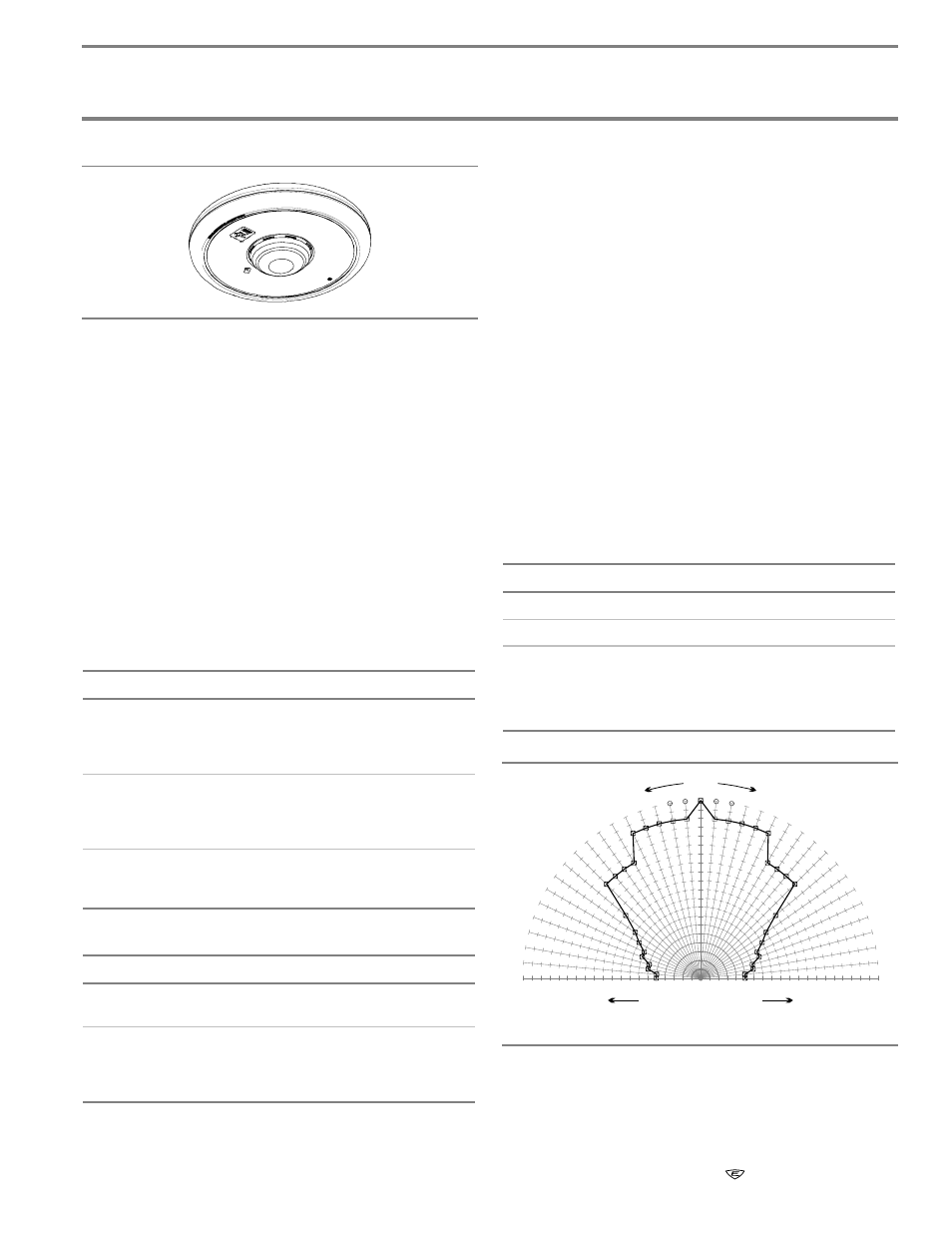
Angle
Percentage of rated output
Horizontal and vertical outputs reflect the same pattern.
Figure 1: UL 1971 minimum light output (% of rating vs. angle)