Edwards Signaling eFSA250 User Manual
Page 272
Appendix D: Applications
260
E-FSA64 and E-FSA250 Technical Reference Manual
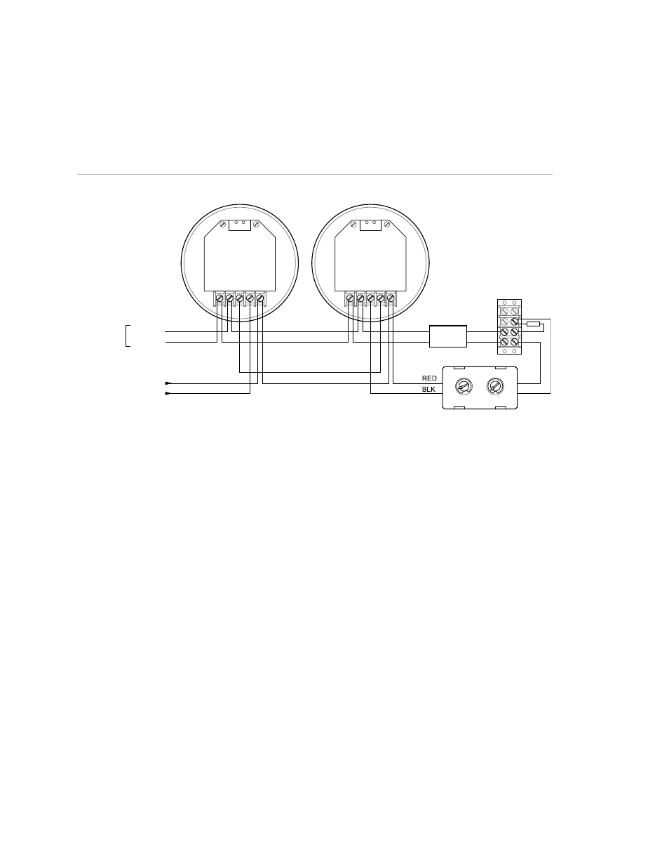
Typical wiring for a local alarm signaling application
The 24 VDC riser that supplies power to the sounder bases is supervised using
an IDC1B Single Input module and a 24 VDC Control Relay.
Figure 57: Typical wiring for a local alarm signaling application
SI
G
+
SI
G
-
D
AT
A-
O
U
T
D
AT
A-
IN
D
AT
A+
IN
/O
U
T
SI
G
+
SI
G
-
D
AT
A-
O
U
T
D
AT
A-
IN
D
AT
A+
IN
/O
U
T
RED
WHT
47 k
EOLR
Ω
Double screw
terminal block
(supplied by installer)
12
11
10
9
4
3
2
1 0
8
5 6 7
0 9
1
8
2
7
3
6
4 5
PAM-1
SLC_IN+
SLC_IN-
24 VDC+
24 VDC-
AUX RISER
FIRST DETECTOR
SB4U
LAST DETECTOR
SB4U
BLU
ORG
Programming sounder bases for a local alarm signaling
application
1. Set the panel’s Event Notification option to Device.
2. Configure the smoke detectors as follows.
Device Type: Smoke or Smoke Heat depending on the detector model
Message Line 1: SMOKE_
other number
Base Type: Sounder
Follow: Head
3. Configure the IDC1B module as follows:
Device type: Monitor
Message Line 1: 24VDC_RISER