11 sensorless operation (without an encoder) – Efficient Networks Siemens Sinamics S120 User Manual
Page 88
Servo control
3.11 Sensorless operation (without an encoder)
Drive Functions
88
Function Manual, (FH1), 07/2007 Edition, 6SL3097-2AB00-0BP4
Example of measuring the speed controller frequency response
By measuring the speed controller frequency response and the control system, critical
resonance frequencies can, if necessary, be determined at the stability limit of the speed
control loop and dampened using one or more current setpoint filters. This normally enables
the proportional gain to be increased (e.g. Kp_n = 3* default value).
After the Kp_n value has been set, the ideal integral action time Tn_n (e.g. reduced from
10 ms to 5 ms) can be determined.
Example of speed setpoint step change
A rectangular step change can be applied to the speed setpoint via the speed setpoint step
change measuring function. The measuring function has preselected the measurement for
the speed setpoint and the torque-generating current.
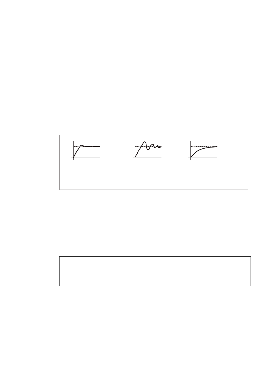
.SBQLVRSWLPXP
.SBQLVWRRODUJH
RYHUVKRRWV
.SBQLVWRRVPDOO
GDPSHGUHVSRQVH
ൺ2.
ൺQRW2.
ൺ2.QRWRSWLPXP
Figure 3-16 Setting the proportional gain Kp
Parameter overview
See "Speed controller".
3.11
Sensorless operation (without an encoder)
NOTICE
The operation of synchronous motors without an encoder must be verified in a test
application. Stable operation in this mode cannot be guaranteed for every application.
Therefore, the user will be solely responsible for the use of this operating mode.
Description
This allows operation without an encoder and mixed operation (with/without encoder).
Encoderless operation with the motor model allows a higher dynamic response and greater
stability than a standard drive with V/f control. Compared with drives with an encoder,
however, speed accuracy is lower and the dynamic response and smooth running
characteristics deteriorate.