5 integration, Function diagrams (see sinamics s list manual) – Efficient Networks Siemens Sinamics S120 User Manual
Page 222
Function modules
7.2 Technology controller
Drive Functions
222
Function Manual, (FH1), 07/2007 Edition, 6SL3097-2AB00-0BP4
7HFBFWUW\SH
S
G
GW
7HFBFWU.S
S
7HFBFWU7Q
S
7HFBFWUO
6HWSRLQW
S
$FWXDOYDOXH
S
5DPSIXQFWLRQJHQHUDWRU
QBVHWS
S
;
VHWS
;
DFW
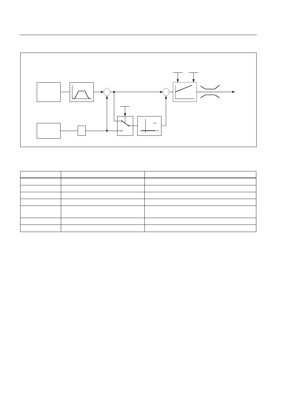
Figure 7-2
Fill level control: controller structure
Table 7-1
Key parameters for the level control
Parameter
Designation
Example
p1155
n_setp1 downstream of RFG
p1155 = r2294 Tec_ctrl output_sig [FP 3080]
p2200
BI: Technology controller enable
p2200 = 1 Technology controller enabled
p2253
CI: Technology controller setpoint 1
p2253 = r2224 Fixed setpoint active [FP 7950]
p2263
Technology controller type
p2263 = 1 D component in fault signal [FP 7958]
p2264
CI: Technology controller actual value
(X
ACTUAL
)
p2264 = r4055 [1] Analog input AI1 of TB30
p2280
Technology controller p-gain
p2280 Determine by optimization
p2285
Technology controller integral action time p2285 Determine by optimization
7.2.5
Integration
The technology controller function is integrated in the system as follows.
Function diagrams (see SINAMICS S List Manual)
● 7950 Fixed values (r0108.16 = 1)
● 7954 Motorized potentiometer (r0108.16 = 1)
● 7958 Closed-loop control (r0108.16 = 1)
Overview of key parameters (see SINAMICS S List Manual)
Fixed setpoints
● p2201[0..n] CO: Technology controller, fixed value 1