Efficient Networks Siemens Sinamics S120 User Manual
Page 165
Vector control
4.20 Bypass
Drive Functions
Function Manual, (FH1), 07/2007 Edition, 6SL3097-2AB00-0BP4
165
0
a
.
.
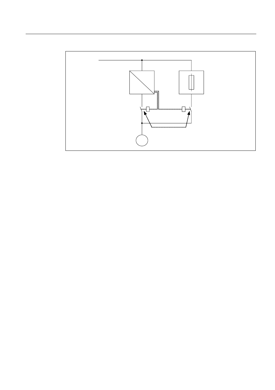
1HWZRUN
&RQYHUWHU
3URWHFWLYHGHYLFH
,QWHUORFNHGDJDLQVW
VLPXOWDQHRXVO\FORVLQJ
Figure 4-28 Circuit example, bypass without synchronization
Activating
The bypass without synchronization (p1260 = 3) can be triggered by the following signals
(p1267):
● Bypass by means of control signal (p1267.0 = 1):
The bypass can be activated by means of a digital signal (p1266) (e.g. from a higher-level
automation system). If the digital signal is withdrawn again after the debypass delay time
has expired (p1263), then a changeover is made to drive converter operation.
● Bypass at speed threshold (p1267.1 = 1):
Once a certain speed is reached, the system switches to bypass (i.e. the converter is
used as a start-up converter). The bypass cannot be connected until the speed setpoint is
greater than the bypass speed threshold (p1265).
The system reverts to converter mode when the setpoint (on the input of the ramp
function generator, r1119) falls below the bypass speed threshold (p1265). The setpoint >
comparison value condition prevents the bypass from being reactivated straight away if
the actual speed is still above the bypass speed threshold (p1265) after switching back to
converter operations.
The bypass time, debypass time, bypass speed variables and the command source for
changing over are set using parameters.
The following signal diagram shows the timing when the bypass switch is on when activating
"bypass for fault".
Example
After activating the bypass function without synchronization (p1260 = 3) the following
parameters still have to be set: