Function diagrams (see sinamics s list manual), Function modules 7.8 closed-loop position control – Efficient Networks Siemens Sinamics S120 User Manual
Page 248
Function modules
7.8 Closed-loop position control
Drive Functions
248
Function Manual, (FH1), 07/2007 Edition, 6SL3097-2AB00-0BP4
37
0RGHO
3RVLWLRQVHWSRLQWEHIRUH
SUHFRQWUROV\PPHWUL]LQJILOWHU
VBGHOWDBPRQWRO
>/8@
S
)ROORZLQJHUURUZLWKLQWROHUDQFH
U
U
)ROORZLQJHUURUG\Q
) )ROORZLQJHUURUWRRKLJK
S
VBDFW
S! >@
3RVLWLRQVHWSRLQWDIWHU
WKHSUHFRQWUROV\PPHWUL]LQJILOWHU
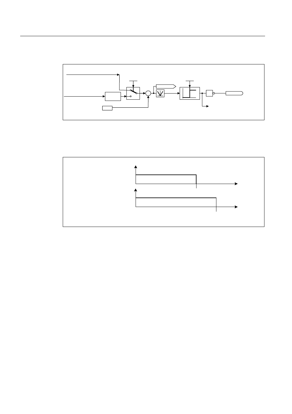
Figure 7-12 Following error monitoring
Following error monitoring is activated via p2546 (following error tolerance). If the absolute
value of the dynamic following error (r2563) is greater than p2546, fault F07452 is output and
bit r2648.8 is reset.
&DPVZLWFKLQJVLJQDO
U
V
V
&DPVZLWFKLQJVLJQDO
U
&DPVZLWFKLQJSRVLWLRQ
S
&DPVZLWFKLQJSRVLWLRQ
S
Figure 7-13 Cam controllers
The position controller has two cam controllers. If cam position p2547 or p2548 is passed in
the positive direction (p2521 > p2547 or 2548), then cam signals r2683.8 and r2683.9 are
reset.
Function diagrams (see SINAMICS S List Manual)
● 4020 Zero-speed / positioning monitoring
● 4025 Dynamic following error monitoring, cam controllers
Overview of key parameters (see SINAMICS S List Manual)
● p2530 CI: LR setpoint position
● p2532 CI: LR actual position value
● p2542 LR standstill window
● p2543 LR standstill monitoring time
● p2544 LR positioning window
● p2545 LR positioning monitoring time