Efficient Networks Siemens Sinamics S120 User Manual
Page 515
Basic information about the drive system
12.10 Rules for wiring with DRIVE-CLiQ
Drive Functions
Function Manual, (FH1), 07/2007 Edition, 6SL3097-2AB00-0BP4
515
Note
This topology does not match the topology created offline by STARTER and must be
changed.
'ULYH
'ULYH
'ULYH
60&
960
60&
60&
HQFRGHU
3RZHUUDWLQJ
&8
0
0
0
'ULYH
60&
0
,QIHHG
;
;
;
;
;
;
;
;
;
;
;
;
;
;
;
;
$FWLYH
/LQH
0RGXOH
6LQJOH
0RWRU
0RGXOH
6LQJOH
0RWRU
0RGXOH
6LQJOH
0RWRU
0RGXOH
;
$FWLYH
,QWHUIDFH
0RGXOH
;
;
;
;
;
;
;
;
;
6LQJOH
0RWRU
0RGXOH
;
;
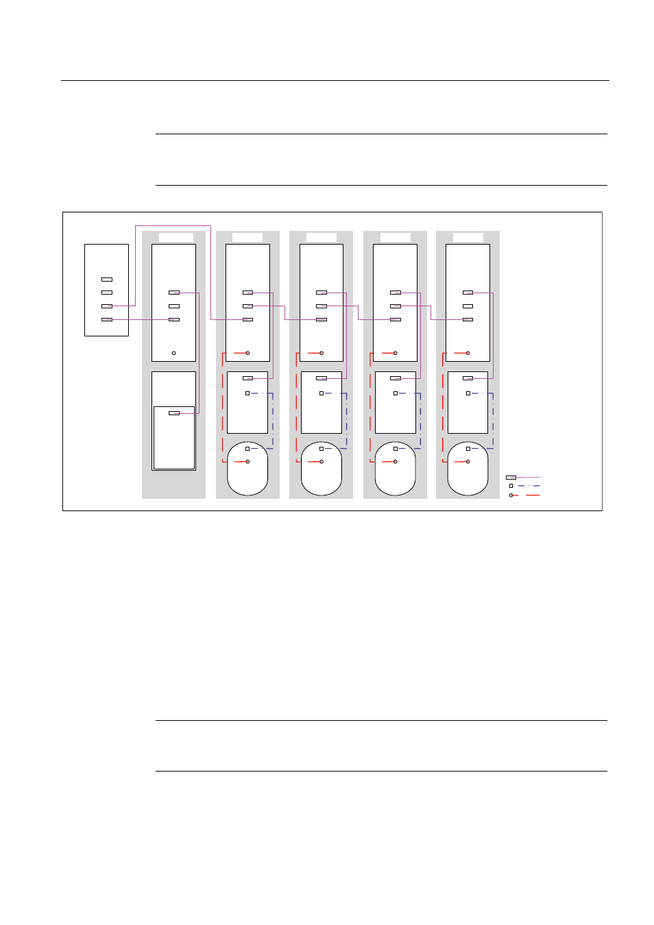
'5,9(&/L4
Figure 12-26 Drive line-up (chassis) with different pulse frequencies
12.10.4 Sample wiring of Vector drives connected in parallel
Drive line-up with two parallel-connected Line Modules and Motor Modules (chassis) of the same type
Parallel-connected Line Modules (chassis) and Motor Modules (chassis) of the same type
can be connected to a DRIVE-CLiQ interface of the Control Unit.
In the following diagram, two Active Line Modules and two Motor Modules are connected to
the X100 and X101 interface.
For further information about parallel connection, see the Function Manual.
Note
This topology does not match the topology created offline by STARTER and must be
changed.