Efficient Networks Siemens Sinamics S120 User Manual
Page 480
Basic information about the drive system
12.4 BICO technology: interconnecting signals
Drive Functions
480
Function Manual, (FH1), 07/2007 Edition, 6SL3097-2AB00-0BP4
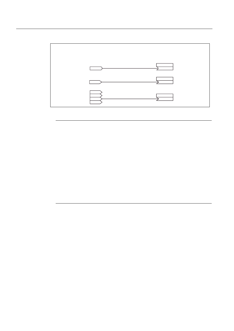
%2%LQHFWRURXWSXW
&2&RQQHFWRURXWSXW
6LJQDOVRXUFH
%,%LQHFWRULQSXW
&,&RQQHFWRULQSXW
6LJQDOVLQN
&2ZLWKRXWLQGH[
&2ZLWKLQGH[
U
,QGH[ >@
U
U
>@
>@
U
>@
U
%2
U
S[[[[\
%,
S[[[[\
>@
&,
S[[[[\
&,
Figure 12-5 Interconnecting signals using BICO technology
Note
A connector input (CI) cannot be interconnected with any connector output (CO, signal
source). The same applies to the binector input (BI) and binector output (BO).
For each CI and BI parameter, the parameter list shows under "data type" the information
on the data type of the parameter and the data type of the BICO parameter.
For CO parameters and BO parameters, only the data type of the BICO parameter is
shown.
Notation:
Data types BICO input: Data type parameter / Data type BICO parameter
Example: Unsigned32 / Integer16
Data types BICO output: Data type BICO parameter
Example: FloatingPoint32
The possible interconnections between the BICO input (signal sink) and the BICO output
(signal source) are listed in the following documents:
References: /LH1/ SINAMICS S List Manual
Chapter "Explanations on parameter list" in table "Possible combinations for BICO
interconnection".
The BICO parameter interconnection can be implemented in different command data sets
(CDS). The different interconnections are activated by switching data sets. Interconnections
across drive objects are also possible.