Efficient Networks Siemens Sinamics S120 User Manual
Page 209
Basic functions
6.14 Position tracking
Drive Functions
Function Manual, (FH1), 07/2007 Edition, 6SL3097-2AB00-0BP4
209
0RWRUORDG
0HDVXULQJJHDU
(QFRGHUV
WHHWK
WHHWK
Figure 6-11 Measuring gearbox
In order to determine the position at the motor/load, in addition to the position actual value of
the absolute encoder, it is also necessary to have the number of overflows of the absolute
encoder.
If the power supply of the control module must be powered-down, then the number of
overflows must be saved in a non-volatile memory so that after powering-up the position of
the load can be uniquely and clearly determined.
Example: Gear ratio 1:3 (motor revolutions p0433 to encoder revolutions p0432), absolute
encoder can count 8 encoder revolutions (p0421 = 8).
3RVLWLRQ
RYHUIORZ
0RWRU
ORDGSRVLWLRQ
2IIVHWIRUHQFRGHURYHUIORZ
3RVLWLRQ
0RWRU
(QFRGHUUDQJH
(QFRGHU
UHYROXWLRQV
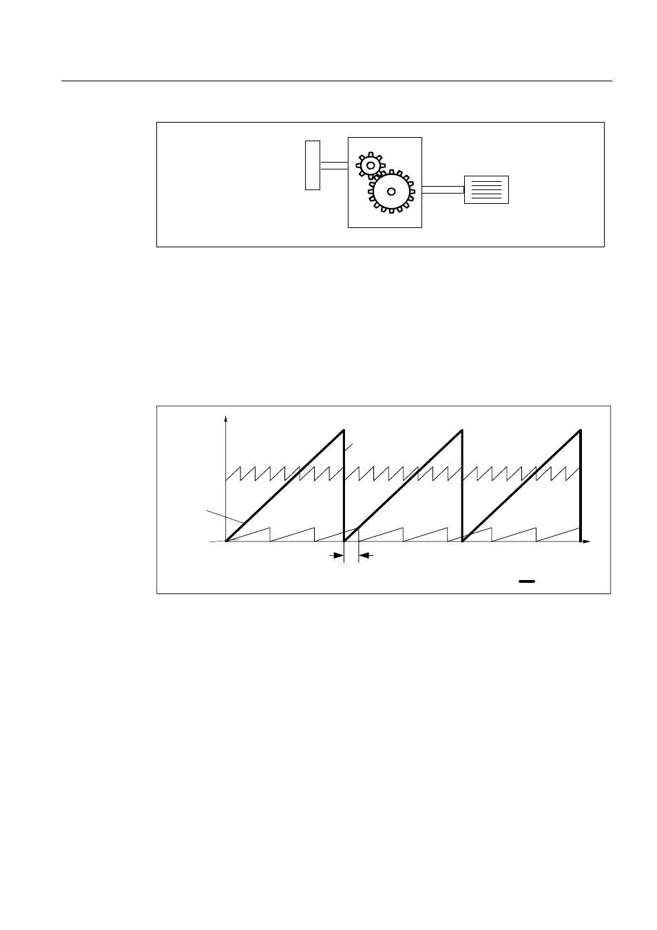
Figure 6-12 Drive with odd-numbered gears without position tracking
In this case, for each encoder overflow, there is a load-side offset of 1/3 of a load revolution,
after 3 encoder overflows, the motor and load zero position coincide again. The position of
the load can no longer be clearly reproduced after one encoder overflow.
If position tracking is activated via p0411.0 = 1, the gear ratio (p0433/p0432) is calculated
with the encoder position actual value (r0483).