9 vdc control, Function diagrams (see sinamics s list manual), Description – Efficient Networks Siemens Sinamics S120 User Manual
Page 133: Vector control 4.9 vdc control, Vdc_max vdc_min
Vector control
4.9 Vdc control
Drive Functions
Function Manual, (FH1), 07/2007 Edition, 6SL3097-2AB00-0BP4
133
setpoint is limited in the Motor Module, this is indicated via the following diagnostic
parameters:
● r1407.8 Upper torque limit active
● r1407.9 Lower torque limit active
indicated.
Function diagrams (see SINAMICS S List Manual)
● 6060 Torque setpoint
● 6630 Upper/lower torque limit
● 6640 Current/power/torque limits
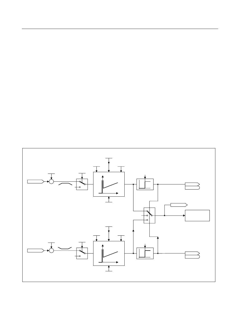
4.9
Vdc control
Description
Control ZSW 1
Vdc_ctrl Kp
p1250
Vdc_ctrl Tn
p1251
Vdc_ctrl t_deriv.
p1252
Vdc_max dyn_factor
p1243
Vdc_ctrl config
p1240
Vdc_max
Vdc_min
Control ZSW 1
Vdc_ctrl Kp
p1250
Vdc_ctrl Tn
p1251
Vdc_ctrl t_
Lead
p1252
Vdc_min dyn_factor
p1247
Vdc_ctrl config
p1240
Vdc_act
Vdc_act
Iq_set
Limit
Vdc_max on_level
r1242
Vdc_min on_level
r1246
Vdc_ctrl_output
2,3
0,1,4,5,6
r0070
–
+
0
0
r0056.15
r0056
0
1
0
r0056.14
r0056
0
1
0
r1258
0
1,3
0,2,4,5,6
–
+
r0070
0
0
Figure 4-13 Vdc control vector