Reference model – Efficient Networks Siemens Sinamics S120 User Manual
Page 126
Vector control
4.5 Speed controller pre-control and reference model
Drive Functions
126
Function Manual, (FH1), 07/2007 Edition, 6SL3097-2AB00-0BP4
Note
The ramp-up and ramp-down times (p1120; p1121) of the ramp function generator in the
setpoint channel should be set accordingly so that the motor speed can track the setpoint
during acceleration and braking. This ensures that speed controller pre-control is functioning
optimally.
The acceleration pre-control using a connector input (p1495) is activated by the parameter
settings p1400.2 = 1 and p1400.3 = 0. p1428 (dead time) and p1429 (time constant) can be
set for balancing purposes.
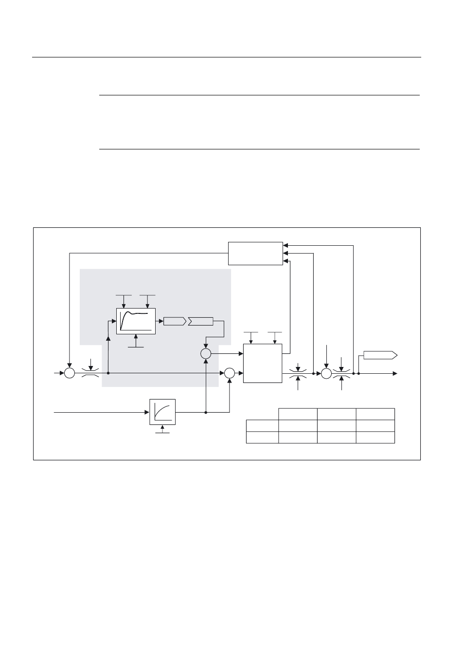
Reference model
6SHHGDFWXDOYDOXH
6SHHG
VHWSRLQW
5HIHUHQFHPRGHOದ3UHFRQWURO
'URRSIXQFWLRQ
LQMHFWLRQ
3,
6SHHG
FRQWUROOHU
7RUTXH
6HWSRLQW
.
S
7
Q
6/9&
9&
.
S
7
Q
7
L
7L
S
S
S
S
S
S
U
U
U
U
U>@
U>@
U
S
U
S
S
S
,
3
Figure 4-9
Reference model
The reference model is activated when p1400.3 = 1 and p1400.2 = 0.
The reference model is used to emulate the path of the speed control loop with a P speed
controller.
The path emulation can be set in p1433 to p1435. It is activated when p1437 is connected to
the output of model r1436.
The reference model delays the setpoint-actual deviation for the integral component of the
speed controller so that transient conditions can be suppressed.