5 integration, Function diagrams (see sinamics s list manual) – Efficient Networks Siemens Sinamics S120 User Manual
Page 228
Function modules
7.4 Extended brake control
Drive Functions
228
Function Manual, (FH1), 07/2007 Edition, 6SL3097-2AB00-0BP4
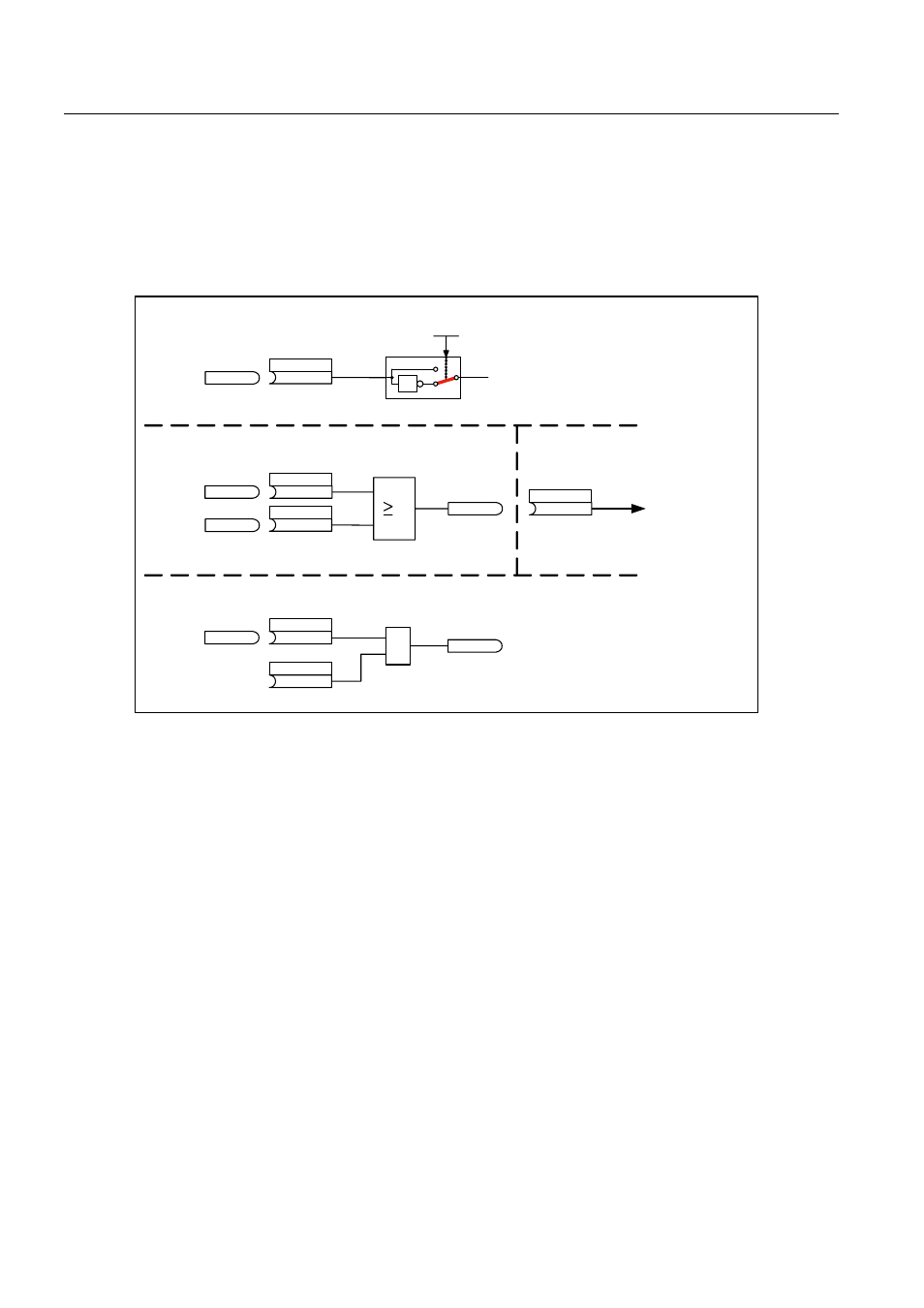
speed controller is immediately enabled - the speed setpoint is enabled after the brake
opening time (p1216). When the master switch is in the zero position, the speed setpoint is
inhibited - the drive is ramp-down using the ramp function generator. The brake closes once
the standstill limit (p1226) has been fallen below. After the brake closing time (p1217), the
speed controller is inhibited (the motor is no longer generating any force). The extended
brake control is used with the modifications described below.
> @
> @
[
]
1
r1229.10
p1279[0]
p1279[1]
r1229.3
<1>
p1275.02 (
1
)
1
0
1
p1224[0]
<1>
r0898.6
&
p1142[C]
(r0899.15)
p1152
<1>
[2501 ]
p0856
3XOVHHQDEOH
H[WEUDNHFRQWURO
25ORJLFRSHUDWLRQ
%UDNH
25ORJLFRSHUDWLRQ
UHVXOW
(QDEOHVSHHGFRQWUROOHU
(QDEOHQBVHW
6HWSRLQWHQDEOH
(QDEOHVSHHGVHWSRLQW
%UDNHWRVWDQGVW
!6HWSRLQWHQDEOHIURPKLJKHUOHYHO
FRQWUROOHUHJ6
(QDEOHVHWSRLQW
0DVWHUVZLWFKPRYHG
>[[[[@)XQFWLRQGLDJUDPQXPEHU
Figure 7-4
Example, operating brake for a crane drive
7.4.5
Integration
The extended brake control function is integrated in the system as follows.
Function diagrams (see SINAMICS S List Manual)
● 2704 Zero speed detection (r0108.14 = 1)
● 2707 Releasing/applying brake (r0108.14 = 1)
● 2711 Signal outputs (r0108.14 = 1)
Overview of key parameters (see SINAMICS S List Manual)
● r0108.14 Extended brake control
● r0899 CO/BO: Status word sequence control