10 rules for wiring with drive-cliq – Efficient Networks Siemens Sinamics S120 User Manual
Page 505
Basic information about the drive system
12.10 Rules for wiring with DRIVE-CLiQ
Drive Functions
Function Manual, (FH1), 07/2007 Edition, 6SL3097-2AB00-0BP4
505
Comparison of topologies at Power On
Comparing the topologies prevents a component from being controlled/evaluated incorrectly
(e.g. drive 1 and 2).
When the drive system is started, the Control Unit compares the detected actual topology
and the electronic type plates with the target topology stored on the CompactFlash card.
You can specify how the electronic type plates are compared for all the components of a
Control Unit via p9906. The type of comparison can be changed subsequently for each
individual component. You can use p9908 for this or right-click in the topology view in the
STARTER tool. All data on the electronic type plate is compared by default.
The following data in the target and actual topologies is compared depending on the settings
made in p9906/9908:
● p9906/9908 = 0: component type, order number, manufacturer, serial number
● p9906/9908 = 1: component type, order number
● p9906/9908 = 2: component type
● p9906/9908 = 3: component class (e.g. Sensor Module or Motor Module)
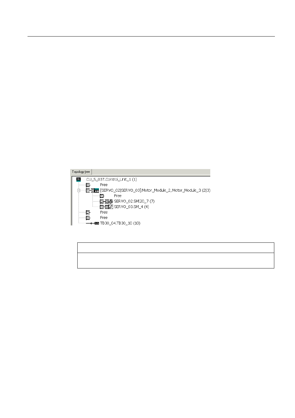
Figure 12-21 Topology view in the STARTER tool
NOTICE
The Control Unit and the Option Board are not monitored. The system automatically
accepts new components and does not output a message.
12.10 Rules for wiring with DRIVE-CLiQ
The following rules apply for wiring components with DRIVE-CLiQ. The rules are subdivided
into DRIVE-CLiQ rules, which must be observed, and recommended rules, which, when
observed, do not require any subsequent changes to the topology created offline in
STARTER.
The maximum number of DRIVE-CLiQ components and the possible wiring form depend on
the following points:
● The binding DRIVE-CLiQ wiring rules
● The number and type of activated drives and functions on the Control Unit in question
● The computing power of the Control Unit in question