Recommended rules – Efficient Networks Siemens Sinamics S120 User Manual
Page 508
Basic information about the drive system
12.10 Rules for wiring with DRIVE-CLiQ
Drive Functions
508
Function Manual, (FH1), 07/2007 Edition, 6SL3097-2AB00-0BP4
– Also change the current controller sampling time and the sampling time of the
inputs/outputs of the DOs not involved so that they again fit into the time grid.
Note
You can call up the "Topology" screen in STARTER to change and/or check the
DRIVE-CLiQ topology for each drive unit.
Note
To enable the function "Automatic configuration" to assign the encoders to the drive,
the recommended rules below must be observed.
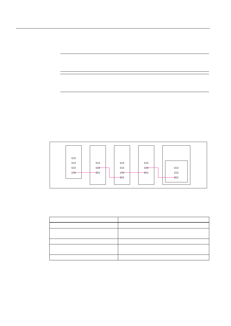
Recommended rules
● The DRIVE-CLiQ cable from the Control Unit must be connected to X200 on the first
booksize power section or X400 on the first chassis power section.
● The DRIVE-CLiQ connections between the power sections must each be connected from
interface X201 to X200/from X401 to X400 on the follow-on component.
● A Power Module with the CUA31 should be connected to the end of the DRIVE-CLiQ line.
&8$
&8
;
;
;
;
;
;
;
;
;
;
;
;;
;;
;;
6LQJOH
0RWRU
0RGXOH
;;
;;
;;
6LQJOH
0RWRU
0RGXOH
3RZHU0RGXOH
%ORFNVL]H
'RXEOH
0RWRU
0RGXOH
Figure 12-23 Example: DRIVE-CLiQ line
● The motor encoder must be connected to the associated power unit.
Table 12-14 Connecting the motor encoder via DRIVE-CLiQ
Component
Connecting the motor encoder via DRIVE-CLiQ
Single Motor Module Booksize
X202
Double Motor Module (booksize)
•
Motor connection X1: Encoder at X202
•
Motor connection X2: Encoder at X203
Single Motor Module Chassis
X402
Power Module Blocksize
•
CUA31: Encoder at X202
•
CU310: Encoder at X100 or via TM31 at X501
Power Module Chassis
X402