Efficient Networks Siemens Sinamics S120 User Manual
Page 511
Basic information about the drive system
12.10 Rules for wiring with DRIVE-CLiQ
Drive Functions
Function Manual, (FH1), 07/2007 Edition, 6SL3097-2AB00-0BP4
511
Servo
Vector V/f (=vector
without speed control
function module)
Vector
Notes on the maximum number of drives that can be controlled by a CU320:
•
In addition, the "Safe Standstill" function can be activated and a TM31 connected.
•
No function modules must be activated.
Rules for FW2.3
● The default sampling times must not be changed.
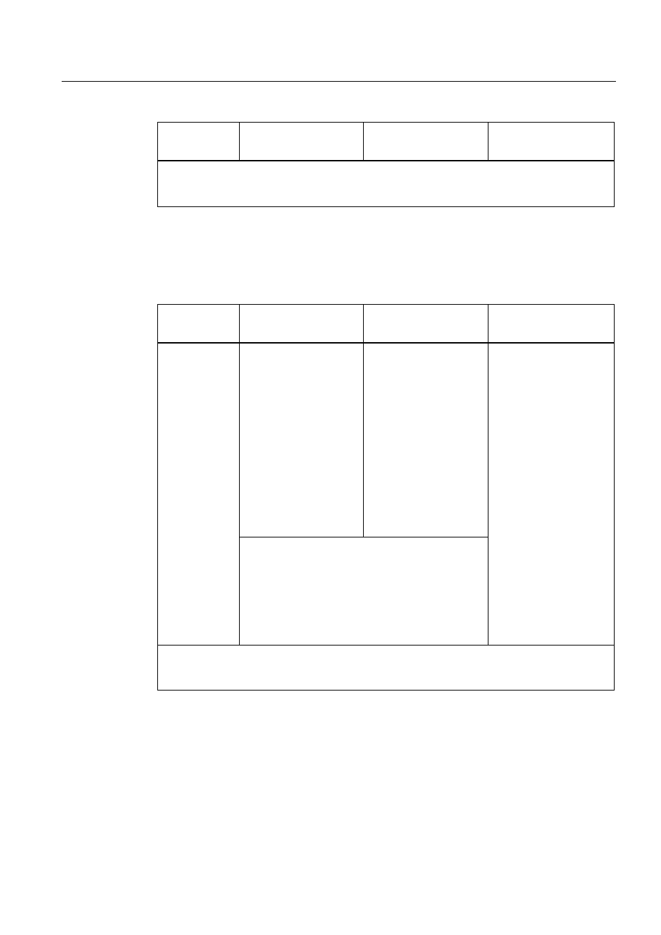
Table 12-18 Maximum number of drives that can be controlled by a Control Unit 320
Servo
Vector V/f (=vector
without speed control
function module)
Vector
1 Active Line Module +
6 Motor Modules
1 Active Line Module +
4 Motor Modules
(sampling time of current
controller 250 µs / speed
controller 1000 µs)
1 Active Line Module +
6 Motor Modules
(sampling time of current
controller 400 µs / speed
controller 1600 µs)
1 Active Line Module +
10 Motor Modules
(sampling time of current
controller 500 µs / speed
controller 4000 µs)
Number of
components
Servo and vector V/f:
1 Active Line Module + 5 Motor Modules
(servo: Current controller 125 µs / speed controller
125 µs vector V/f:
sampling time of current controller 250 µs with max.
2 V/f drives
Sampling time of current controller 400 µs with more
than 2 V/f drives)
1 Active Line Module +
2 Motor Modules
(sampling time of current
controller 250 µs / speed
controller 1000 µs)
1 Active Line Module +
4 Motor Modules
(sampling time of current
controller 400 µs / speed
controller 1600 µs)
Notes on the maximum number of drives that can be controlled by a CU320:
•
In addition, the "Safe Standstill" function can be activated and a TM31 connected.
•
No function modules must be activated.