3 active infeed closed-loop control chassis – Efficient Networks Siemens Sinamics S120 User Manual
Page 24
Infeed
1.1 Active Infeed
Drive Functions
24
Function Manual, (FH1), 07/2007 Edition, 6SL3097-2AB00-0BP4
1.1.3
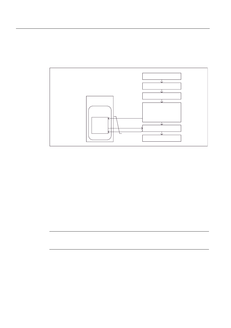
Active Infeed closed-loop control Chassis
Schematic structure
6XSSO\V\VWHPGDWD
0DQLSXODWHG
YDULDEOHV
$FWXDOYDOXHV
'&OLQN
6XSSO\V\VWHP
)XVHV
0DLQVZLWFK
$FWLYH,QWHUIDFH0RGXOH
ZLWKSUHFKDUJLQJ
ZLWK960
:LWKOLQHILOWHU
ZLWKOLQHUHDFWRU
'5,9(&/L4
,QIHHG
$FWLYH
)LUPZDUH
&RQWURO8QLW
$FWLYH/LQH0RGXOH
&KDVVLV
Figure 1-2
Schematic structure of Active Infeed
Operating mode of Active Infeed closed-loop control for Chassis Active Line Modules.
Active Line Modules Chassis only function in Active Mode.
In Active Mode, the DC link voltage is regulated to a variable setpoint (p3510), which results
in a sinusoidal line current (cosφ = 1).
The DC link voltage setpoint (p3510) is preset depending on the supply voltage (p0210)
using the equation p3510 = 1.5 * p0210.
Commissioning
The device supply voltage (p0210) must be parameterized during commissioning. The
necessary line filter (p0220) is preset.
When it is first switched on with a new/modified network, an automatic controller setting
should be implemented using the line/DC link identification routine (p3410).
Note
In a supply system without regenerative feedback capability (e.g. generators), regenerative
operation must be inhibited via the binector input p3533.
The DC link voltage (p3510) can be set within the following limits:
● Upper limit:
– Maximum DC link voltage (p0280)
– Product of line voltage (p0210) and max. step-up factor (r3508)
● Lower limit: Supply voltage (p0210) multiplied by 1.42