Applications, Setup – Rockwell Automation 1426 PowerMonitor 5000 Unit User Manual
Page 54
54
Rockwell Automation Publication 1426-UM001F-EN-P - November 2013
Chapter 4
Metering
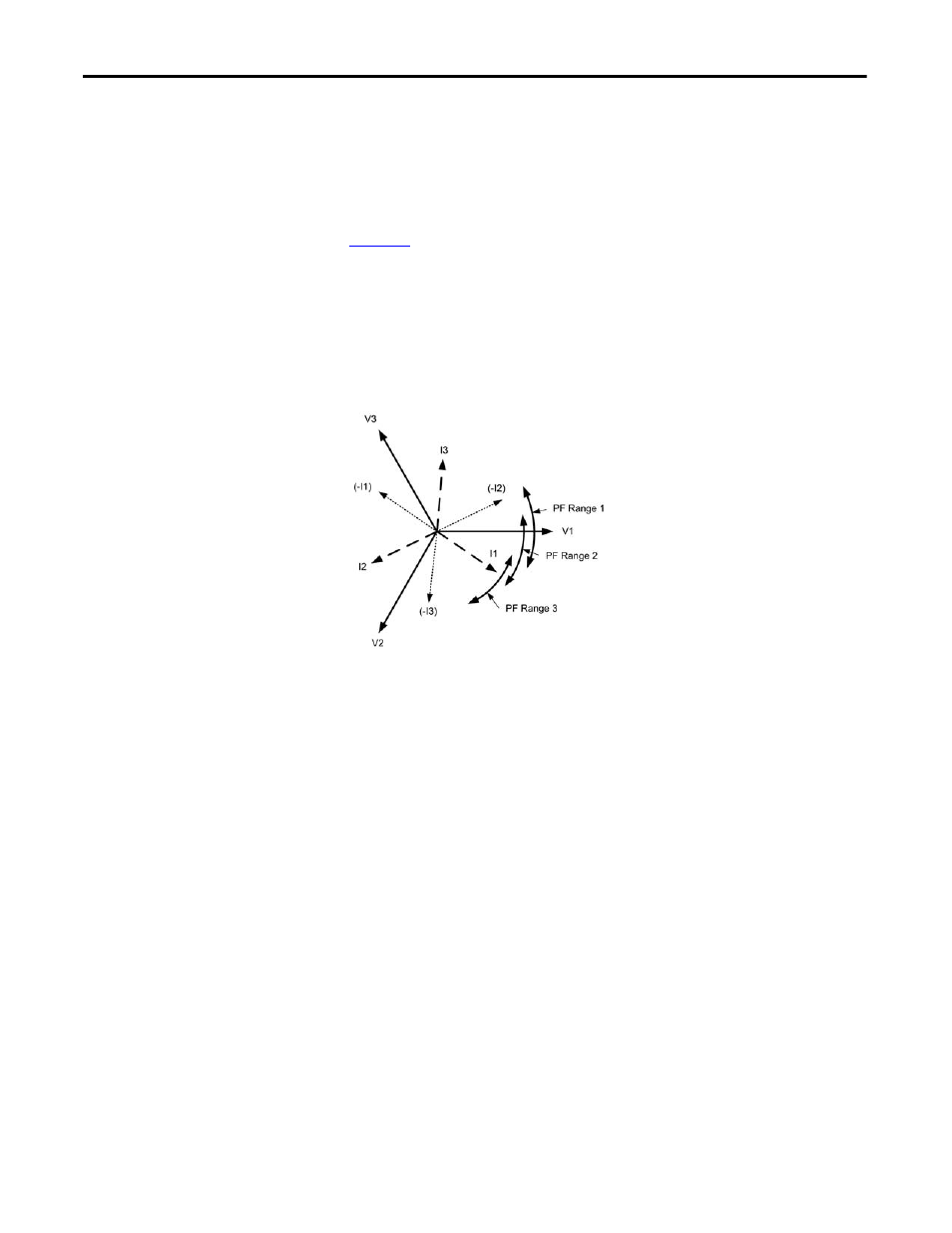
The power monitor displays wiring diagnostic status results for all three power
factor ranges when a command is issued. You decide which power factor range
applies based upon your knowledge of the circuit and its load characteristics. You
can expect more reliable wiring diagnostic results when the circuit is operating in
a normal condition, that is, not especially lightly loaded.
illustrates the part power factor plays in wiring diagnostics. The PF
ranges show the I1 phase angle limits for each range. The phasor diagram shows
the fundamental voltage and currents in a three-phase, 4-wire system operating
with a lagging power factor of roughly 85%. In this example, ranges 2 and 3
wiring diagnostic can return good results, but range 1 can incorrectly indicate
that all currents are inverted and displaced by a phase, as shown by the –I1, -I2
and –I3 phasors.
Figure 21 - Power Factors and Wiring Diagnostics
In addition to wiring diagnostics on command, the PowerMonitor 5000 unit
updates voltage and current magnitude and phase angle data continually. These
values are used by FactoryTalk EnergyMetrix RT software to display a system
phasor diagram.
Wiring diagnostic results can also be used for automatic virtual wiring correction,
as described in the next section.
Applications
This applies to all models.
Setup
Only basic metering setup is required.