Powermonitor 5000 unit dimensions, Panel mounting, Powermonitor 5000 unit dimensions panel mounting – Rockwell Automation 1426 PowerMonitor 5000 Unit User Manual
Page 18
18
Rockwell Automation Publication 1426-UM001F-EN-P - November 2013
Chapter 2
Install the PowerMonitor 5000 Unit
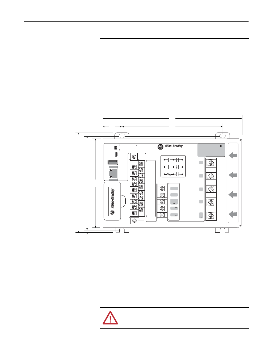
PowerMonitor 5000 Unit Dimensions
Panel Mounting
Follow these steps for panel mounting a PowerMonitor 5000 unit.
1.
Use the power monitor as a template and mark pilot holes on your panel.
2.
Drill pilot holes for M4 or #8 screws.
IMPORTANT
Use caution not to block the ventilation slots of the power monitor. All wiring,
wire ways, enclosure components, and other obstructions must be a minimum
of 50 mm (2.0 in.) from the top and bottom of the unit to provide ventilation
and electrical isolation. Units can be mounted side-by-side.
Note that access to the USB device port is required for initial configuration of
the power monitor and can be required for eventual administration and
maintenance. Consider safe and convenient access to the power monitor front
panel when planning the installation location.
Virtual Wiring
Correction
---- S1
S2
---- S3
S4
---- S com
S com
---- K
Y
---- Z
R1 O
---- R1 com
R1 C
---- R2 O
R2 com
---- R2 C
R3 O
---- R3 com
R3 C
Module
status
Network
status
Config Lock
EtherNet/
IP
Power
USB
Device
USB
Host
LNK
ACT
I 1
I 2
I 3
I 4
L1
L2
GND
24V
com
Scom
S n
Internal
24 VDC
K
Y
Z
Rx O
Rx com
Rx C
V1
V2
V3
VN
VG
C
O
M
M
U
N
IC
A
T
IO
N
P
O
R
T
185
7 . 29
25
1 . 00
132
5 . 23
132
5 . 20
3 .3
0 . 13
124
4 . 88
118
4 . 65
PowerMonitor 5000
Mounting Hole Tolerance:
±0.4 mm (0.016 in.)
Dimensions are in mm/in.
Depth: 178/7.0
ATTENTION: During mounting of all devices, make sure that all debris (such as
metal chips or wire strands) is kept from falling into the power monitor. Debris
that falls into the module could cause damage when the device is energized.