Configuration.instance – Rockwell Automation 1426 PowerMonitor 5000 Unit User Manual
Page 233
Rockwell Automation Publication 1426-UM001F-EN-P - November 2013
233
PowerMonitor 5000 Unit Data Tables
Appendix A
Configuration.Instance
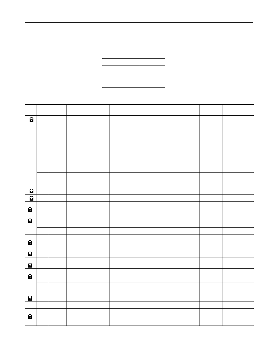
Table 43 - Table Properties
CIP
102
No. of Elements
43
Length in Words
80
Data Type
Varies
Data Access
Read/Write
Table 44 - Configuration.Instance Data Table
Start
Byte
Size Type
Tag
Name
Description
Units
Range
0
1
SINT
MeterMode
Configures the input wiring for metering.
0 = Demo
1 = Split Phase
2 = Wye
3 = Delta 2 CT
4 = Delta 3 CT
5 = Open Delta 2 CT
6 = Open Delta 3 CT
7 = Delta Gnd B Ph 2 CT
8 = Delta Gnd B Ph 3 CT
9 = Delta High Leg
Mode
0…9
1
SINT
Pad01
For alignment purpose
INT
Pad02
For alignment purpose
4
4
Real
VLinePTPrimary
The primary voltage value of the PT transformer
V
0…1,000,000
8
4
Real
VLinePTSecondary
The secondary voltage value of the PT transformer
V
0…690
12
4
Real
ILineCTPrimary
The primary ampere value of the CT transformer
A
0…1,000,000
16
1
SINT
ILineCTSecondary
The secondary ampere value of the CT transformer
A
5
1
SINT
Pad03
2
INT
Pad04
For alignment purpose
20
4
Real
VNPTPrimary
The primary voltage value of the PT transformer
V
0…1,000,000
24
4
Real
VNPTSecondary
The secondary voltage value of the PT transformer
V
0…690
28
4
Real
I4CTPrimary
The primary ampere value of the CT transformer
A
0…1,000,000
32
1
SINT
I4CTSecondary
The secondary ampere value of the CT transformer
A
5
1
SINT
Pad05
For alignment purpose
2
INT
Pad06
For alignment purpose
36
4
Real
NominalVToVVoltage
Nominal voltage value or voltage rating of the system being metered.
V
0…1,000,000
40
4
DINT
Pad07
For alignment purpose
N/A
0…0
44
4
Real
NominalFreq
Nominal frequency of the system.
50=50 Hertz
60=60 Hertz
Hertz
50 or 60