ElmoMC SimplIQ Digital Servo Drives-Bell Command Reference User Manual
Page 309
0
2
4
6
8
10
0
500
1000
1500
2000
2500
3000
3500
4000
4500
5000
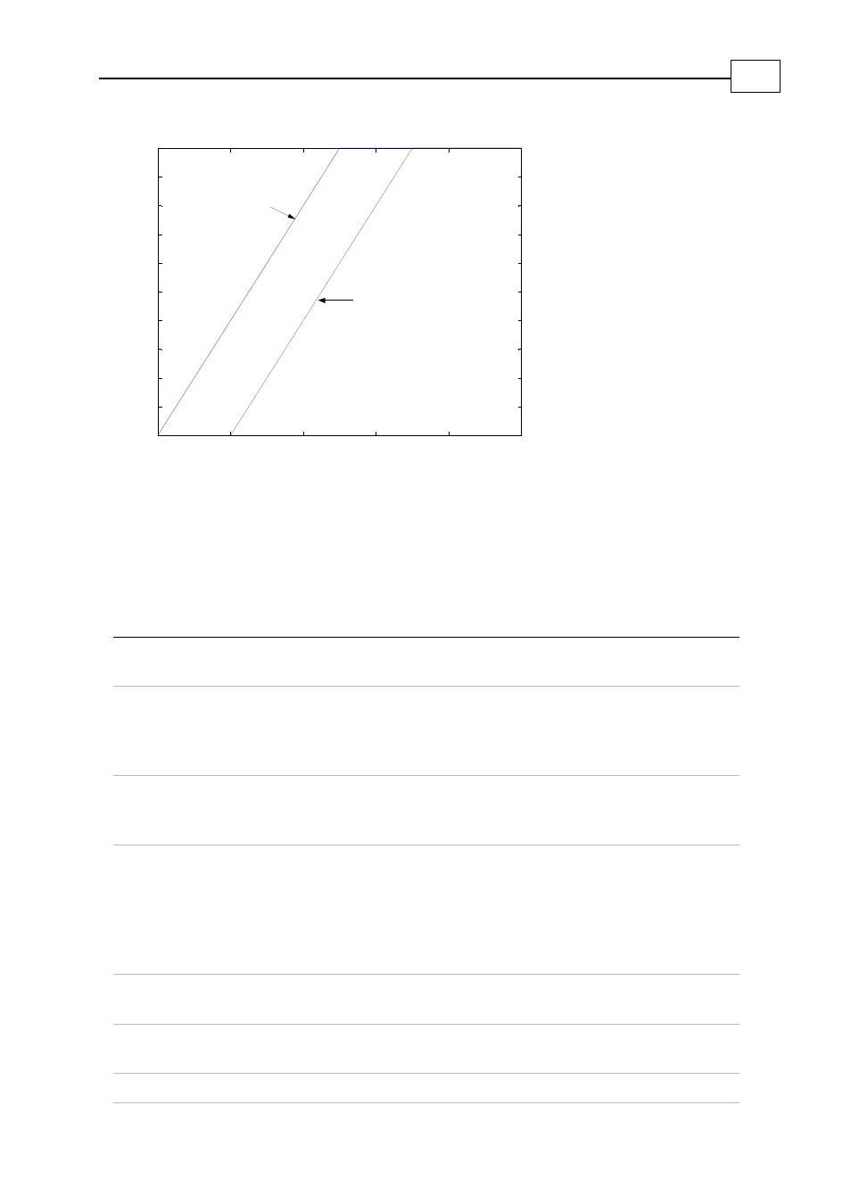
Speed C ommand
Time
Triggered on B G with
0% pre-trigger delay
Triggered on B G with
20% pre-trigger delay
Figure 10-2: Pre-trigger Delay
In this example, the recorder works for 10 seconds. In such a case, a pre-trigger delay of
20% requires 2 seconds, in order to acquire the pre-trigger data. A
BG
command set for
less than 2 seconds after the
RR=3
will be missed.
The following table lists the trigger parameters.
RP[N] Description
Definition
RP[0] Recorder time quantum 0: Speed controller sampling time (4 * TS µsec)
1: Torque controller sampling time (TS µsec)
RP[1] Trigger variable
Similar to RC, but only 1 bit may be non-zero.
The trigger variable does not need to be a recorded
variable. For example, RV[1]=17, RP[1]=1 defines a
trigger that is made on signal #17 (stator field angle).
RP[2] Pre-trigger storage, in
percent
0 to 100 (percent).
RP[3] Trigger type
0: Immediate
1: BG
2: Positive slope
3: Negative slope
4: Window
5: Trigger on digital input
RP[4] Level 1
Level of positive slope trigger, or high side of window
trigger.
RP[5] Level 2
Level of negative slope trigger, or low side of window
trigger.
RP[6]
Digital input trigger polarity.
SimplIQ for Steppers Application Note
Development Aids
MAN-STECR (Ver. 1.1)
110