Simpliq – ElmoMC SimplIQ Digital Servo Drives-Bell Command Reference User Manual
Page 210
Σ
Analog input
AS[2]
-
AG[1]
Σ
PWM
(YA[4]=5 or YA[4]=6)
or speed
(YA[4]=0 or YA[4]=2)
FR
Hard
stop,
FLS
,
RLS
Enable logic
Digital inputs
Speed
command
Σ
Software jog
reference
Soft stop
Enable logic
Filter
KV[44] ...
KV[55]
DV[2]
Acceele
ration
lim it er
RM
DV[4]
Digital inputs
DV[5]
SD, HL[2]
LL[2]
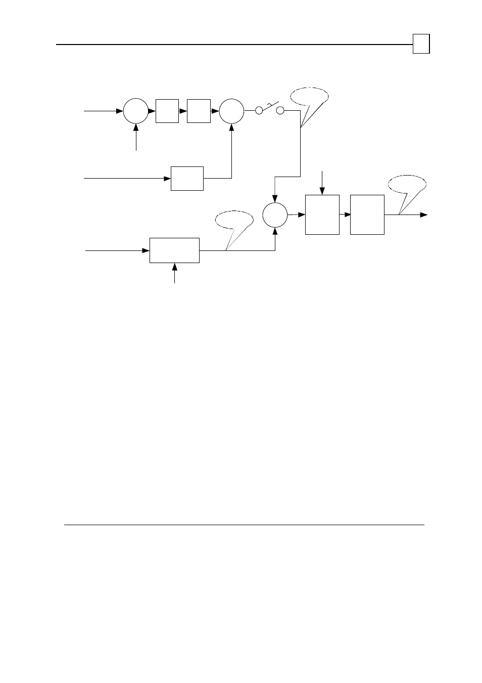
Figure 3-2: Unit Mode 2 (Speed) Structure
The DV[2] command reports the combined (software and analog input) speed demand,
after being further processed for acceleration and speed limiting, and for the switch
actions RLS, FLS and STOP.
DV[4] and DV[5] retrieve the external and software components of DV[2], respectively.
The analog or PWM input is most useful when the
SimplIQ
drive serves as an inner
controller, embedded in an external control loop. The auxiliary encoder speed input
enables the drive to issue speed commands relative to a conveyor or other moving object.
If you do not use the analog input for the torque command, set RM = 0, in order to avoid
noise.
The filter is optional. You can design a linear arbitrary filter of an order up to 4, and use it
to filter the analog input for extra smoothness.
The auxiliary speed reference is generated according to the block diagram that follows.
The parameters relevant to auxiliary speed command generation are:
Parameters Description
AG[2]
Analog input gain, counts/second/volt
AS[1] Analog
offset
FR[2] Follower
gain
KV[44]…KV[55]
Filter for analog input – refer to the KV command in the command
reference
SimplIQ for Steppers Application Note
Unit Modes
MAN-STECR (Ver. 1.1)
11