Unit mode 4: dual feedback mode – ElmoMC SimplIQ Digital Servo Drives-Bell Command Reference User Manual
Page 219
• For open loop mode, HT[2] and HT[3] are defined for PN[4] counts/electrical rev. or
PN[4]
× S/4 counts/mechanical rev. where S is the number of steps.
• For closed loop mode, HT[2] and HT[3] are defined for the encoder counts.
The varying notch filter is for compensating the oscillations that follow from open loop
operation. It notches the frequency
T
r
K I
J
ω =
out, using the inertia in PF[16], the
T
K
of
PF[2], and the damping of PF[17].
The current I in the calculation of
r
ω
does not account for current driven by analog input.
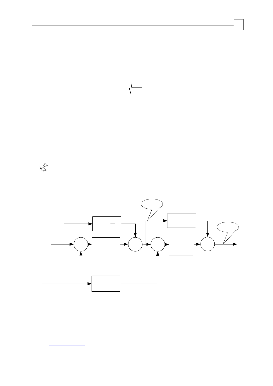
3.5. Unit Mode 4: Dual Feedback Mode
Dual feedback mode is used when different sensors are used for speed/commutation
and for position. This mode is commonly used when the motor drives the load
through a reduction gear. The controlled position is that of the load. The inner loop
controls speed, with much higher bandwidth.
A sensor mounted directly on the motor allows much better control bandwidth
than a load sensor. This is because the motor sensor is much less susceptible to delay
and backlashes.
Σ
Position
command
Load sensor
feedback
-
Σ
Speed
estimator
Speed
controller
Position
Controller
DV[2]
Motor sensor
feedback
Speed
feedback
-
DV[1]
[2]
d
FF
dt
Σ
Σ
[1]
d
FF
dt
Figure 3-7: Dual Feedback Mode (UM=4)
For further details:
The
Position Reference Generator
The
Position controller
The
Speed controller
SimplIQ for Steppers Application Note
Unit Modes
MAN-STECR (Ver. 1.1)
20