Inductor voltage corrections, Current controller pi + filter implementation, 2 inductor voltage corrections – ElmoMC SimplIQ Digital Servo Drives-Bell Command Reference User Manual
Page 301
The back EMF, for a single motor phase, is modeled by a normalized lookup table, and
the motor torque coefficient
T
K
, given by PF[2].
Both the lookup–tables and
T
K
are measured by the setup and tuning tools.
9.3.2
Inductor Voltage Corrections
Inductance compensations are required to decouple the D and the Q controllers, i.e.
prevent Q channel control effort leaks to the D channel and vice versa.
The correction uses the inductance value in PF[1].
9.4.
Current Controller PI + Filter
Implementation:
There are two identical current controllers: one for the Q channel and one for the D
channel.
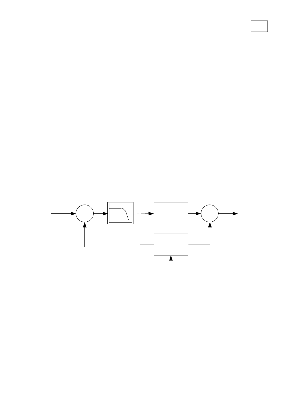
Each current controller implements the following block diagram:
Σ
Current command
(torque for IQ, 0 for ID)
LPF, 1
st
order
KP[1]
[1]
KI
dt
∫
Σ
Anti windup correction
Output:
Vq or Vd
PF[13]
-
IQ or ID
Figure 22: Current PI controller + filter
The filter, with its bandwidth PF[13], is for attenuating high frequency noise.
KP[1] and KI[1] are the proportional and integral gains, respectively.
The “Anti Windup correction” means that after limiting the actual controller output
(the limiting depends on the output of the other channel and also on the available DC
bus voltage), the integrator state is trimmed to avoid excessive overshoot that voltage
limits may cause.
The units of KP[1] are Volt/Amp
The units of KI[1] are Volt/(Amp Sec)
SimplIQ for Steppers Application Note
The Current Controller
MAN-STECR (Ver. 1.1)
102